Rs485 network wiring, Rs485 network wiring -30, On drive connections – Rockwell Automation 22C PowerFlex 400 AC Drive FRN 1.xx - 7.xx User Manual
Page 42
1-30
Installation/Wiring
PowerFlex 400 Adjustable Frequency AC Drive FRN 1.xx - 7.xx User Manual
Publication 22C-UM001I-EN-P
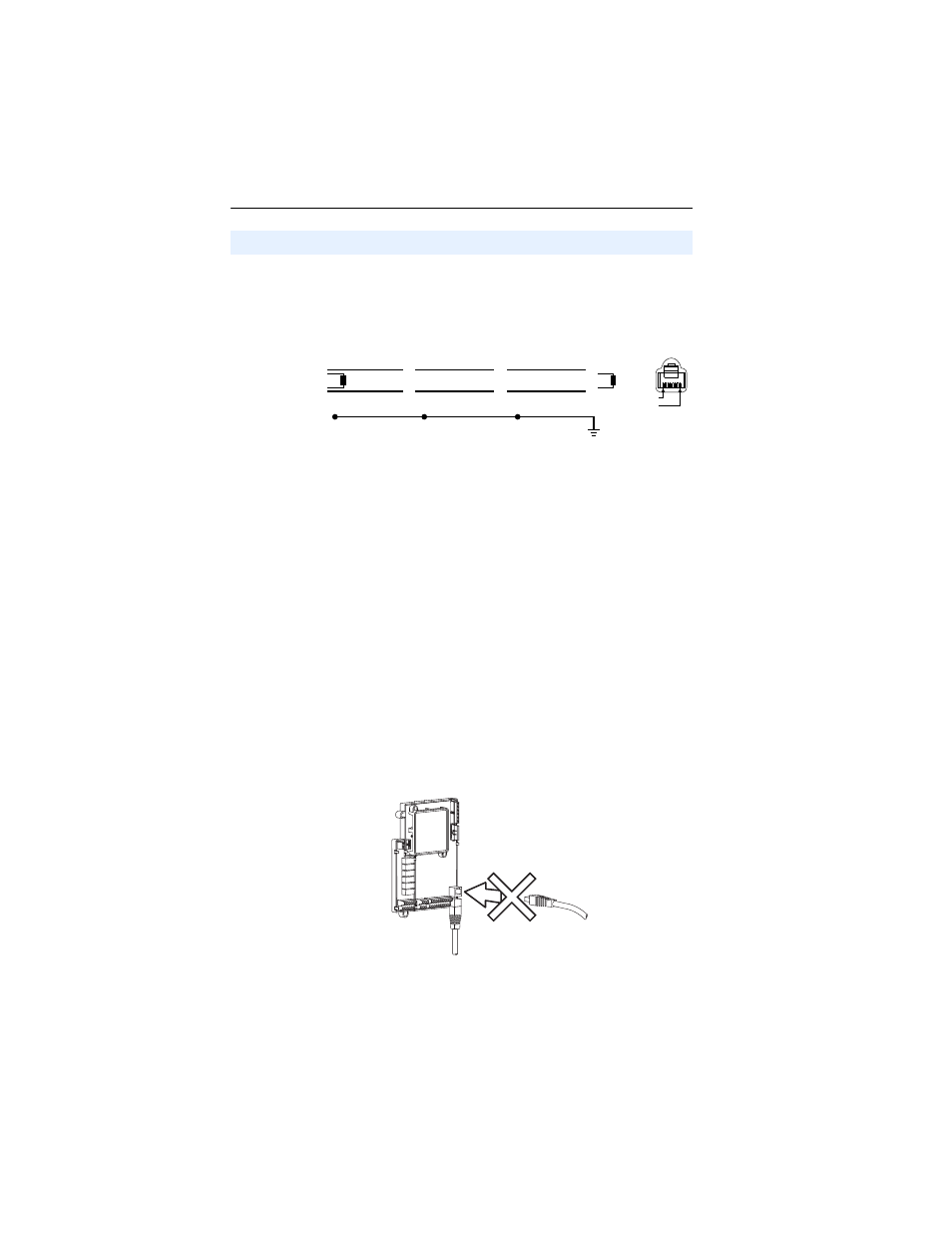
Network wiring consists of a shielded 2-conductor cable that is
daisy-chained from node to node.
Figure 1.12 Network Wiring Diagram
Only pins 4 and 5 on the RJ45 plug should be wired. The other pins on
the PowerFlex 400 RJ45 socket contain power, etc. for other Rockwell
Automation peripheral devices and must not be connected.
Wiring terminations on the master controller will vary depending on the
master controller used and “TxRxD+” and “TxRxD-” are shown for
illustration purposes only. Refer to the master controller’s user manual
for network terminations. Note that there is no standard for the “+” and
“-” wires, and consequently Modbus device manufacturers interpret
them differently. If you have problems with initially establishing
communications, try swapping the two network wires at the master
controller.
On Drive Connections
PowerFlex 400 Frame D, E, F, G and H drives are equipped with two
RS485 (DSI) ports. One is accessible via an access door when the cover
is on and one is only accessible with the cover off. When one of these
ports has a Rockwell DSI device connected, the second port cannot be
used.
Figure 1.13 Frame D, E, F, G and H RS485 Ports
RS485 Network Wiring
Master
PowerFlex 400
Node 1
4
5
PowerFlex 400
Node 2
4
5
PowerFlex 400
Node "n"
4
5
TxRxD+
TxRxD-
TxRxD+
TxRxD-
TxRxD+
TxRxD-
NOTE: The shield should be grounded at ONLY ONE location.
Shield
Shield
Shield
120 ohm resistor
120 ohm resistor
FRONT
PIN 8
PIN 1
RS485 (DSI) Network Connection
Second RS485 (DSI) Connection