System. refer to, Figure 103-2, For a drawing of the soneplex t1 repeater (rlx) – ADC Soneplex Broadband System User Manual
Page 287
ADCP-61-471 • Issue 4 • June 2000 • Section 2: Operation and Maintenance
2-264
© 2000, ADC Telecommunications, Inc.
TAD-103
Page 2 of 3
G= DS1 errors at HLXR are reported as T1-1-X-X-2 NEND PM and alarms.
Report measures the actual DS1 performance as received on transmission
from CSU H.
- OR -
DS1 errors at HLXR are reported as T1-1-X-X-2 FEND PM and alarms from
CSU H via the PRM in the FDL (Facility Data Link).
H = External CSU at H will inject PRM back to G reporting DS1 Far End Alarms.
Errors are accumulated in the transmission of the DS1 from A to H transmit
direction.
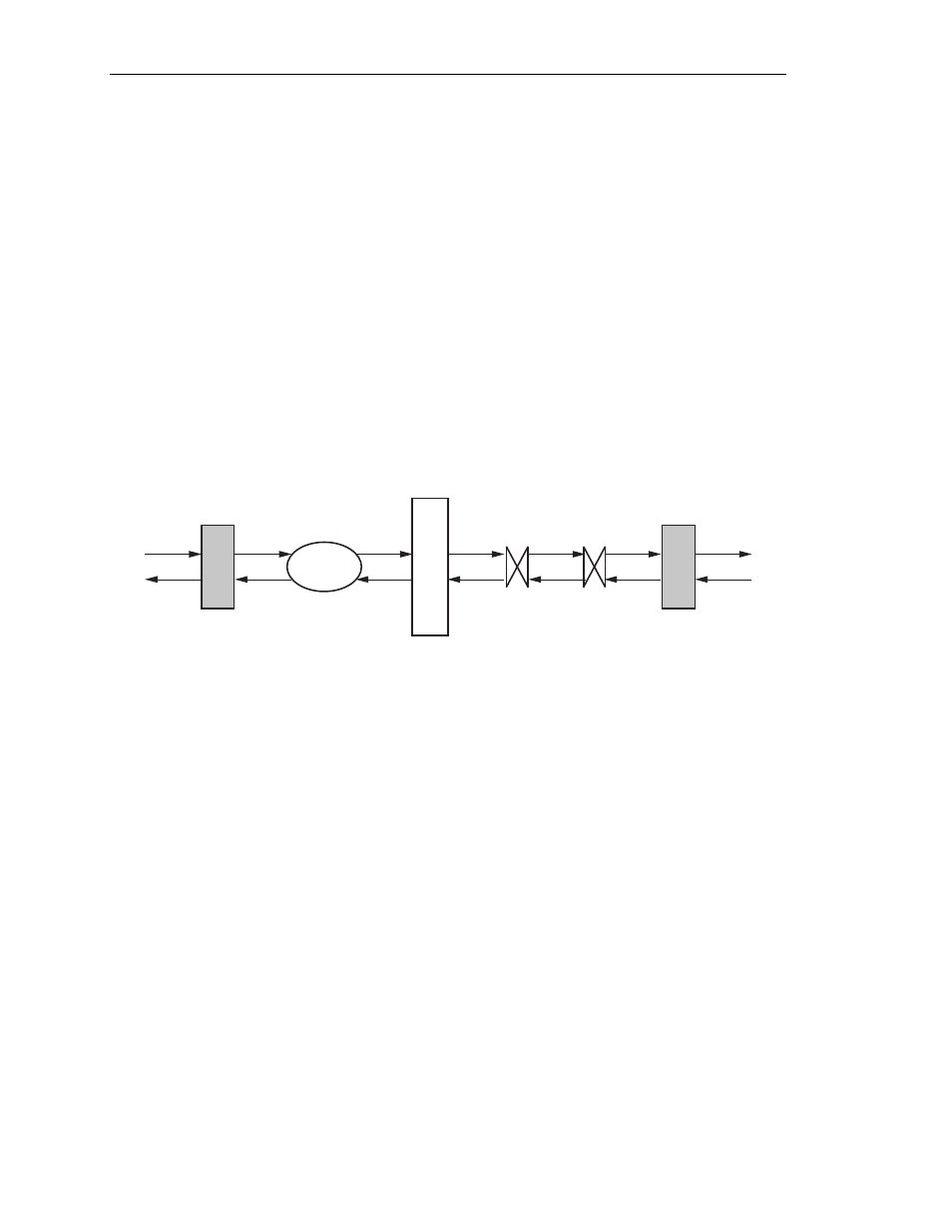
Soneplex T1 Repeater (RLX) System
A
H
CSU
CSU
RLX
B
G
14863-A
NETWORK
DS1
DS1
T1 REPEATER SPAN
Figure 103-2. Location of Critical Alarm Points on Soneplex RLX System
A = External CSU that will inject PRM (Performance Report Messages) back to B
reporting all DS1 Far End Alarms. This is due to corrupted data received at A
and reported back to B via the PRM in the FDL (Facility Data Link).
B = RLX DS1 input monitors T1-1-X-X-1 NEND PM and alarms. Report measures
the actual DS1 performance as received on transmission from CSU A.
- OR -
RLX DS1 input monitors T1-1-X-X-1 FEND PM and alarms from CSU A via
the PRM in the FDL (Facility Data Link).
G= RLX DS1 input monitors T1-1-X-X-2 NEND PM and alarms. This report
measures the actual DS1 performance as received on transmit from CSU H.
- OR -
RLX DS1 input monitors T1-1-X-X-2 FEND PM and alarms from CSU H via
the PRM in the FDL (Facility Data Link).
H= External CSU at H will inject PRM back to G reporting DS1 Far End Alarms.
This is due to corrupted data accumulated in the transmission of the DS1 from
A to H transmit direction.