ADC Soneplex Broadband System User Manual
Page 276
ADCP-61-471 • Issue 4 • June 2000 • Section 2: Operation and Maintenance
2-253
© 2000, ADC Telecommunications, Inc.
TAD-101
Page 5 of 9
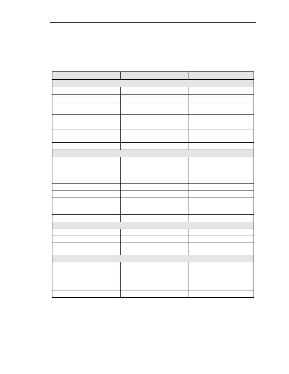
Table 101-1. Soneplex Broadband System (V5) Specifications, continued
PARAMETER
SPECIFICATION
REMARKS
A2 RLX Module
Frame Format
SF, ESF, SLC96, and unframed
Frequency
1.544 Mbps ± 200 bps (130 ppm)
Input Signal Level
0 dB to –33 dB
Clock recovery range for loop
timing.
Line Code
AMI or B8ZS
Output Line Buildout Settings
0.0, 7.5, 15.0, and 22.5 dB
Output Signal Range
Up to 3,000 feet (914.4 meters)
Up to 6,000 feet (1,828.8 meters)
with ideal cable conditions.
Span Power
60 mA, –140 VDC max.
Up to 7 or 14 watts
Version B RLX / RLXIOR Modules
Frame Format
SF, ESF, SLC96 and unframed
Frequency
1.544 Mbps ± 130 ppm
Input Signal Level
0 dB to –33 dB
Clock recovery range for loop
timing
Line Code
AMI or B8ZS
Output Signal LBO Settings
0.0, 7.5, 15.0 and 22.5 dB
Output Signal Range
Up to 3,000 feet (914.4 meters)
over 22 AWG wire
Up to 6,000 feet (1,828.8
meters) depending on cable
characteristics
Span Power
60 mA, ±140 VDC maximum
Up to 8 or 16 watts
Streaker Module
Internal Batteries
4 AAA 1.5 volt (6 VDC)
Mounted on PCB
Jack Type
Bantam
System Input Voltage Range
–
42.5 to
–
56.5 VDC
–
48 VDC nominal
TAU Module
DS1 Jack Access Jack Type
Bantam
Electrical Interface
Bipolar
Impedance
100 ohms nominal
Line Code
AMI or B8ZS
Controlled by front panel switch
Line Rate
1.544 Mbps ± 130 ppm max.
(continued)