Dlp-570 – ADC Soneplex Broadband System User Manual
Page 240
ADCP-61-471 • Issue 4 • June 2000 • Section 2: Operation and Maintenance
2-217
© 2000, ADC Telecommunications, Inc.
DLP-570
Page 7 of 18
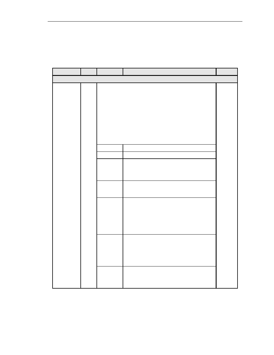
Table 570-1. RTAU Configuration Fields, continued
FIELD
TYPE
OPTIONS
DESCRIPTION
DEFAULT
EQUIPMENT SETUP FIELDS, continued
Mode
Toggle
OVERVIEW: Valid access modes and the resulting configurations are shown in
(RTAU Test Configuration Block Diagram),
(SPLTB and SPLTA),
(Typical Round-Robin Test Configuration),
(Typical End Test Configuration),
(SPLTF and SPLTE),
(Typical Point-to-Point Test Configuration),
(LOOPF and LOOPE).
In addition, when the Mode field change is saved by pressing the Enter or Return
key, the MPU will instruct the DS3 MUX to drop and insert the selected circuit.
DISABLE
MONE
Non-intrusive monitor access to the A pair.
MONF
Non-intrusive monitor access to the B pair.
SPLTA
SPLTA mode indicates a split in the A transmission path
with a TSG (Test Signal Generator) connected in the F
direction, and an SPD (Signal Presence Detector) connected
to the signal from the E direction.
SPLTB
SPLTB mode indicates a split in the B transmission path
with a TSG connected in the E direction, and an SPD
connected to the signal from the F direction.
SPLTE
SPLTE mode indicates a split in both the A and B
transmission paths. An SPD is connected to the line incoming
from the E direction and a TSG is connected to the line
outgoing to the E direction. The line outgoing in the F
direction is connected to a QRSS source, and the line
incoming from the E direction is terminated by the nominal
characteristic impedance of the line.
SPLTF
SPLTF indicates a split in both the A and B transmission paths
with a TSG connected to the line outgoing to the F direction,
and an SPD connected to the line incoming from the F
direction. The line outgoing in the E direction is connected to
a QRSS source, and the line incoming from the E direction is
terminated by the nominal characteristic impedance of the line.
SPLTEL
SPLTEL indicates a split in both the A and B paths and connects
an SPD to the line incoming from the E direction and a TSG to
the line outgoing in the E direction similar to SPLTE mode. The
signal in the F direction is looped back.
(continued)