ADC Soneplex Broadband System User Manual
Page 275
ADCP-61-471 • Issue 4 • June 2000 • Section 2: Operation and Maintenance
2-252
© 2000, ADC Telecommunications, Inc.
TAD-101
Page 4 of 9
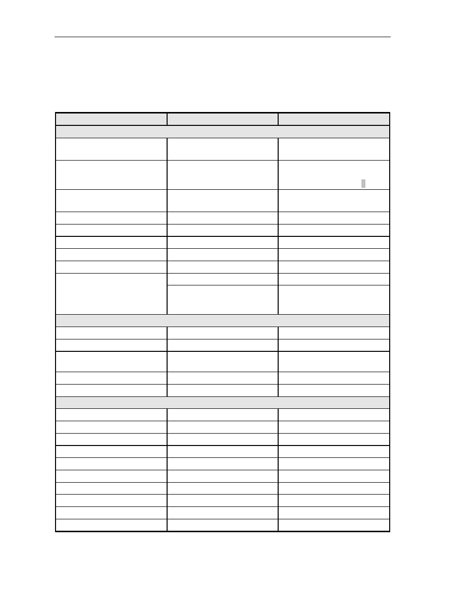
Table 101-1. Soneplex Broadband System (V5) Specifications, continued
PARAMETER
SPECIFICATION
REMARKS
Version D and later HLXRs; HLXR 3192
DS1 Interface:
Input / Output Signals
Per ANSI T1-403
Frequency
1.544 Mbps
HLXR 3192 only: ±200 bps
received signal tolerance;
±50 bps generated signals
HDSL Interface:
Format
Two 784 kbps full duplex pairs
2B1Q
Impedance
135 ohms
Loop Loss
<35 dB
196 kHz
Loop Type
Two pair, single or mixed gauges
With or without bridged taps
Output Signal Level
+13.5 dBm
Return Loss
>20 dB
40 to 200 kHz
Power
–42.5 to –56.5 VDC (local)
Version D HLXR only
–
130 VDC or ±130 VDC (line)
Constant voltage differential
between loops 1 and 2 can vary
from 42 VDC to 260 VDC
Version A and Version B HRXs
Impedance
135 ohms
Input Voltage
Up to ±130 VDC nominal
Loop Loss Allowed
Up to 35 dB
HLXC to HRX, first HRX to
second HRX, and HRX to HLXR
Output Signal Level
13.5 ±0.5 dBm
Power Consumption
6.2 watts (max. per repeater)
All power dissipated in the unit.
ODS2 Module
Fiber Cable
9/125 µm single mode
Nominal
Line Rate
6.312 Mbps ± 20 ppm
Number of Fibers
Two single mode
Per ODS2 module
Operating Wavelength
1300 nm ± 40 nm
Optical Budget
22.0 dB (minimum)
Optical Connector
FC or SC type (Tx/Rx)
Optical Transmit Power
–7 dBm ± 2 dB
Average power
Receive Device
PIN Photodiode
Receiver Dynamic Range
–5 to –31 dBm @10
-9
BER
Transmit Device
Laser
(continued)