Campbell Scientific CR3000 Micrologger User Manual
Page 326
Section 8. Operation
326
Input filters, however, attenuate the amplitude (voltage) of the signal. The
amount of attenuation is a function of the frequency passing through the filter.
Higher-frequency signals are attenuated more. If a signal is attenuated enough, it
may not pass the state transition thresholds required by the detection device (listed
in table Pulse-Input Channels and Measurements
(p. 40)
). To avoid over
attenuation, sensor output voltage must be increased at higher frequencies. As an
example, table Filter Attenuation of Frequency Signals
(p. 326)
lists low-level ac
frequencies and the voltages required to overcome filter attenuation.
For pulse-input channels P1 – P4, an RC input filter with an approximate 1.2-
μs
time constant precedes the inverting CMOS input buffer. The resulting amplitude
reduction is illustrated in figure Amplitude Reduction of Pulse-Count Waveform
(p.
For a 0- to 5-Vdc square wave applied to a pulse channel, the maximum
frequency that can be counted in high-frequency mode is approximately 250 kHz.
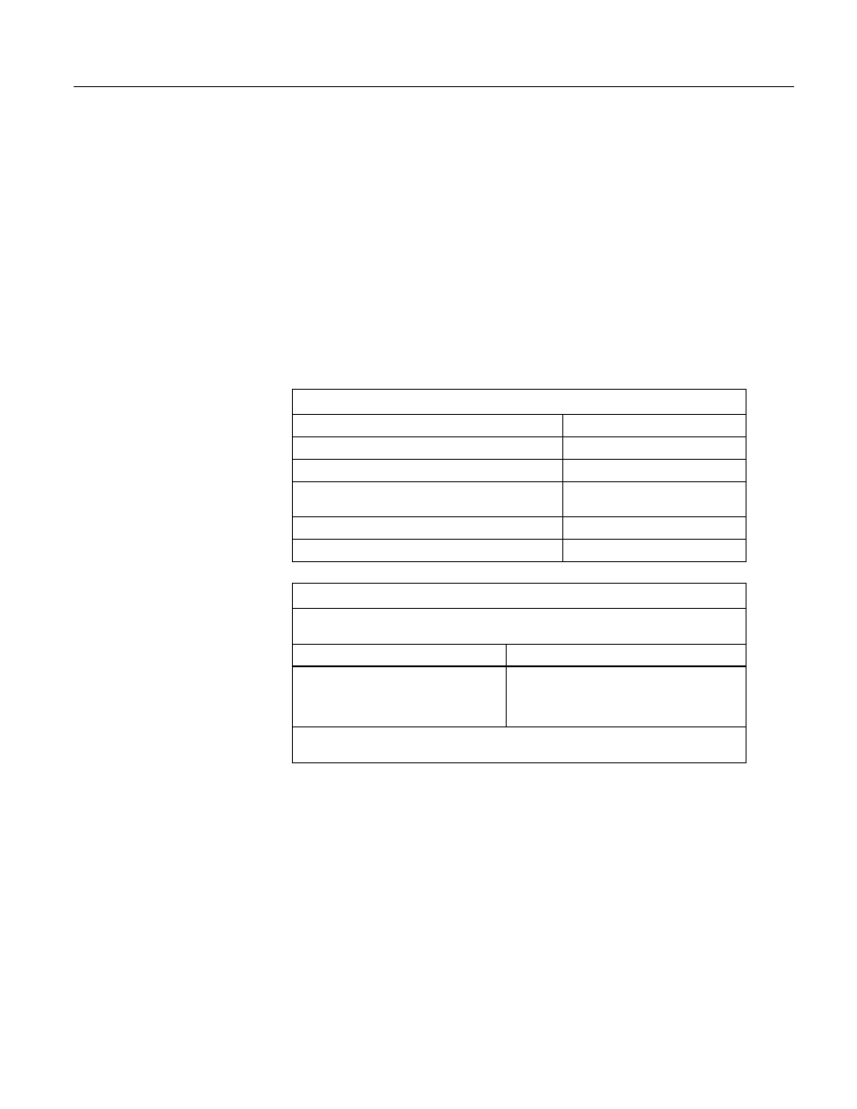
Table 76. Time Constants (τ)
Measurement
τ
Pulse channel, high-frequency mode
1.2
Pulse channel, switch-closure mode
3300
Pulse channel, low-level ac mode
See table Filter Attenuation of
Frequency Signals
(p. 326)
footnote
Digital I/O, high-frequency mode
0.025
Digital I/O, switch-closure mode
0.025
Table 77. Filter Attenuation of Frequency Signals.
As shown for low-level ac inputs, increasing voltage is required at increasing frequencies to
overcome filter attenuation on pulse-input channels*.
ac mV (RMS)
Maximum Frequency
20
200
2000
5000
20
200
10,000
20,000
*8.5-ms time constant filter (19 Hz 3 dB frequency) for low-amplitude signals. 1-ms time
constant (159 Hz 3 dB frequency) for larger (> 0.7 V) amplitude signals.