1 pulse-input channels (p1 - p4), 1 high-frequency pulse (p1 - p4), Figure 102: pulse input channels – Campbell Scientific CR3000 Micrologger User Manual
Page 320
Section 8. Operation
320
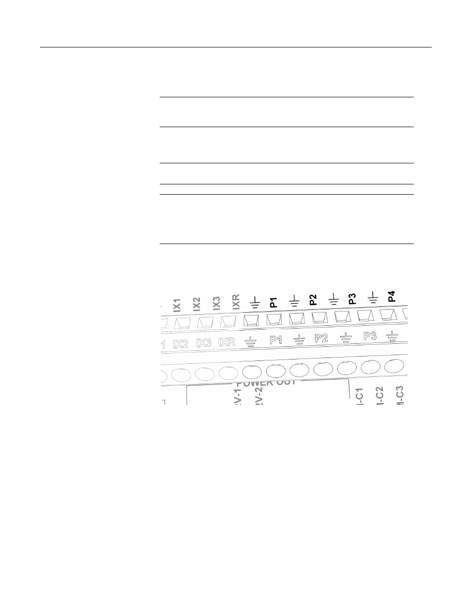
8.1.5.1 Pulse-Input Channels (P1 - P4)
Read More! Review pulse counter specifications at CR3000 Specifications
.
Review pulse counter programming in CRBasic Editor Help for the PulseCount()
instruction.
Dedicated pulse-input channels (P1 through P4), as shown in figure Pulse-Input
Channels
(p. 320),
can be configured to read high-frequency pulses, low-level ac
signals, or switch closures.
Note Input-channel expansion devices for all input types are available from
Campbell Scientific. Refer to Sensors and Peripherals for more information.
Caution Maximum input voltage on pulse channels P1 through P4 is
±20 V. If
pulse inputs of higher than
±20 V need to be measured, third-party external-signal
conditioners should be employed. Contact a Campbell Scientific applications
engineer if assistance is needed. Under no circumstances should voltages greater
than
±50 V be measured.
Figure 102: Pulse input channels
8.1.5.1.1 High-frequency Pulse (P1 - P4)
High-frequency pulse inputs are routed to an inverting CMOS input buffer with
input hysteresis. The CMOS input buffer is an output zero level with its input
≥
2.2 V, and an output one level with its input
≤ 0.9 V. When a pulse channel is
configured for high-frequency pulse, an internal 100-k
Ω pull-up resistor to 5 Vdc
on the P1 or P2 input is automatically employed. This pull-up resistor
accommodates open-collector (open-drain) output devices for high-frequency
input.