1 input limits – Campbell Scientific CR3000 Micrologger User Manual
Page 281
Section 8. Operation
281
instructions BrFull(), BrFull6W(), BrHalf4W(), TCDiff(), VoltDiff () and
Resistance () instructions instructions perform DIFF voltage measurements.
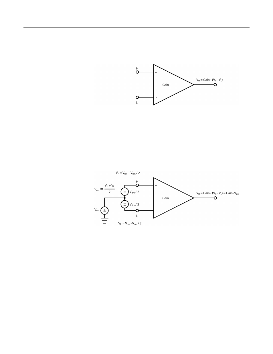
Figure 88: PGI amplifier
A PGIA processes the difference between the H and L inputs, while rejecting
voltages that are common to both inputs. Figure PGIA with Input Signal
Decomposition
(p. 281),
illustrates the PGIA with the input signal decomposed into a
common-mode voltage (V
cm
) and a DIFF-mode voltage (V
dm
). The common-mode
voltage is the average of the voltages on the V
H
and V
L
inputs, i.e., V
cm
= (V
H
+
V
L
)/2, which can be viewed as the voltage remaining on the H and L inputs with
the DIFF voltage (V
dm
) equal to 0. The total voltage on the H and L inputs is
given as V
H
= V
cm
+ V
dm
/2, and V
L
= V
cm
– V
dm
/2, respectively.
Figure 89: PGIA with input signal decomposition
8.1.2.1 Input Limits
The input limits specification is the voltage range, relative to CR3000 ground,
which both H and L input voltages must be within to be processed correctly by the
PGIA. Input limits for the CR3000 are ±5 Vdc. Input voltages in which V
H
or V
L
are beyond the ±5 Vdc input limits may suffer from undetected measurement
errors. The term “common-mode range”, which defines the valid range of
common-mode voltages, is often used instead of “input limits.” For DIFF voltages
that are small compared to the input limits, common-mode range is essentially
equivalent to input limits. Yet from figure PGIA with Input Signal Decomposition
(p. 281),
Common‐Mode Range = ± 5 Vdc – | V
dm
/2 |,
indicating a reduction in common-mode range for increasing DIFF signal
amplitudes. For example, with a 5000 mV DIFF signal, the common-mode range