NORD Drivesystems BU0750 User Manual
Page 95
BU 0750 GB-3311
Subject to technical amendments
95
Parameter
Setting value / Description / Note
Parameter
set
Available with option
14 = Actual value process controller *, activates the process controller, analog input 1 is
connected to the actual value encoder (compensator, air can, flow volume meter, etc.). The
mode (0-10 V or 0/4-20 mA) is set in P401.
15 = Setpoint process controller *, as for Function 14, however, the setpoint is specified (e.g.
by a potentiometer). The actual value must be specified via a different input.
16 = Process controller lead *, adds an adjustable additional setpoint after the process
controller.
Note: Further details regarding the process controller can be found in Section 10.2
17 = Reserved
18 = Curve travel control, the slave communicates its actual speed to the master
*) The limits of these values are set by the parameters >Minimum frequency auxiliary setpoints<
P410 and >Maximum frequency auxiliary setpoints< P411.
P401
Analog input mode 1
BSC
STD
MLT
0...3
[ 0 ]
0 = 0
– 10V limited: An analog setpoint smaller than the programmed adjustment 0% (P402)
does not lead to undershooting of the programmed minimum frequency (P104). This therefore
does not lead to a reversal of the direction of rotation.
1 = 0 - 10V: also allows output frequencies which are below the programmed minimum frequency
(P104) if a setpoint is present, which is smaller than the programmed matching of 0% (P402).
This allows reversal of the direction of rotation using a simple voltage source and
potentiometer.
E.g. internal setpoint with reversal of direction of rotation: P402 = 5V, P104 = 0Hz,
Potentiometer 0
–10V
Rotation direction change at 5V in mid-range setting of the
potentiometer.
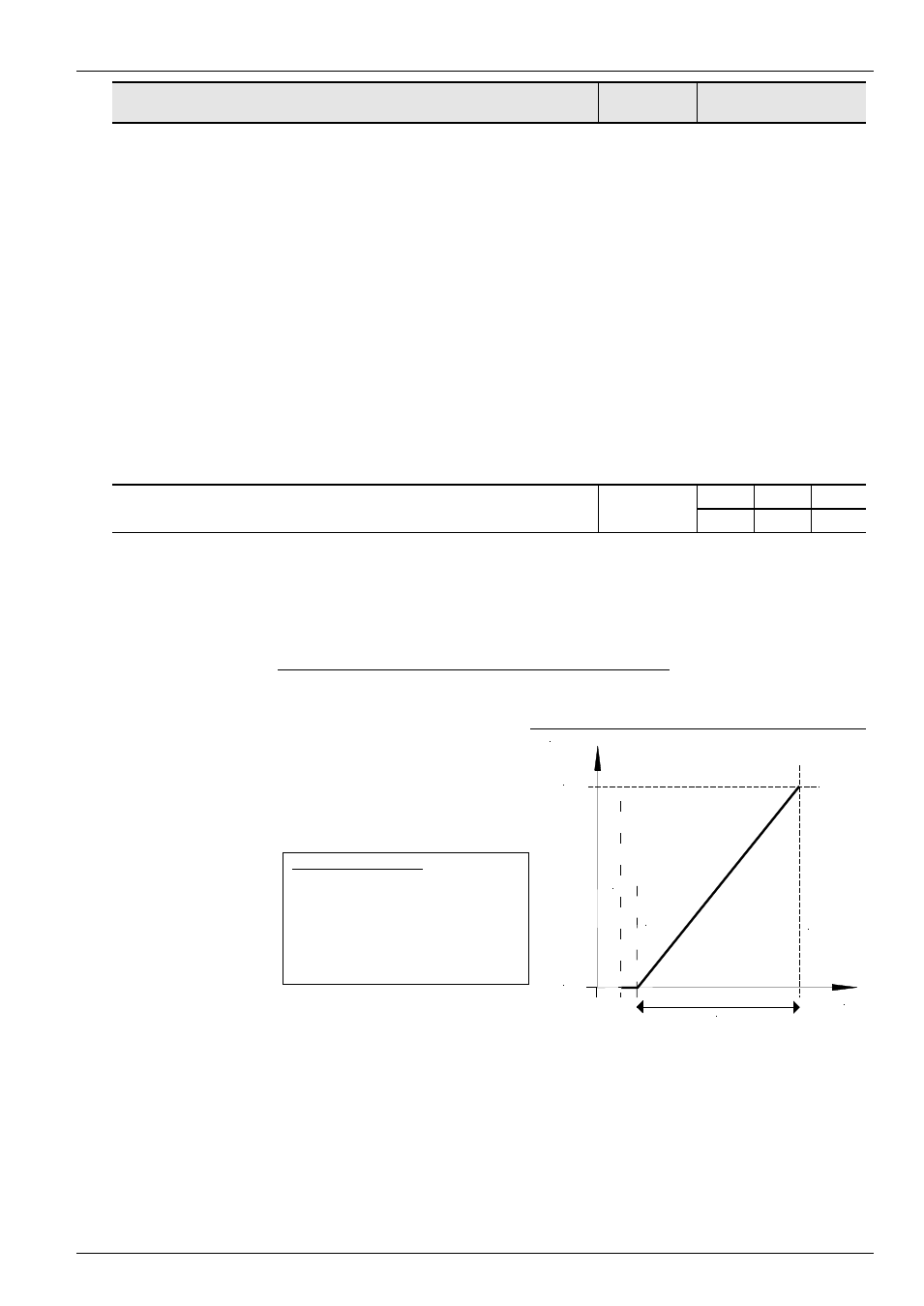
2 = 0 – 10V monitored: If the minimum
adjusted setpoint (P402) is undershot by
10% of the difference value from P403
and P402, the FI output switches off As
soon as the setpoint is greater than
[P402 - (10% * (P403 - P402))] it delivers
an output signal again.
E.g. setpoint 4-20mA:
P402: Adjustment 0% = 1V; P403:
Adjustment 100% = 5V; -10%
corresponds to -0.4V; i.e. 1...5V
(4...20mA) normal operating zone,
0.6...1V = minimum frequency
setpoint, below 0.6V (2.4mA) output
switches off.
f / Hz
P104
(fmin)
P105
(fmax)
P
4
0
3
=
1
0
.0
V
P
4
0
2
=
2
.0
V
= 8.0V
U/V
O
F
F
=
2
.0
V
-
1
0
%
*
8
.0
V
=
1
.2
V
.... continued on next page