6 multi i/o 20ma customer unit – NORD Drivesystems BU0750 User Manual
Page 45
BU 0750 GB-3311
Subject to technical amendments
45
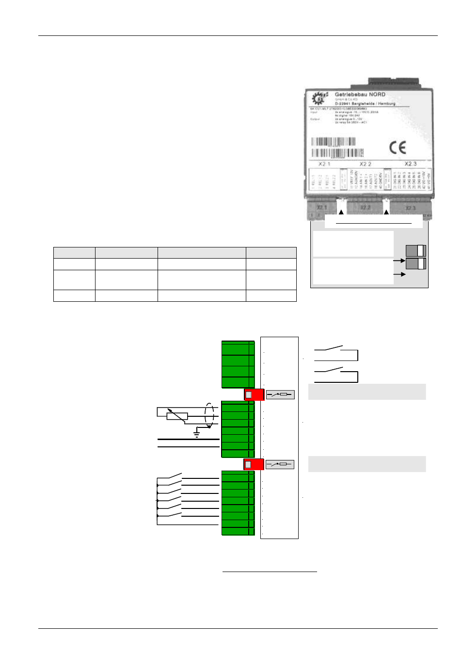
3.3.6 Multi I/O 20mA Customer Unit
(SK CU1-MLT-20mA, Part No.: 278200015)
The Multi I/O (Customer Unit) Multi I/O 20mA provides the highest
functionality of digital and analog signal processing. There are 2
differential analog input and 6 digital inputs available for control of
the frequency inverter. Both analog inputs can process signals
from 0...10V, 0...20mA (4...20mA) or
-
10V...+10V.
Two programmable and scaleable analog outputs 0/4..20mA
enable actual operating parameters to be transmitted to a display
device or process control system.
Via the two relay contacts, a brake control can be actuated or
warnings can be transferred to another system.
The digital inputs of the multi I/O 20mAcannot process analog
setpoints! (See also Section "Control terminals", P420-P425)
NOTE: All control voltages are based on a common reference potential!
Potentials AGND /0V and GND /0V are internally linked in the device.
The maximum total current 5/15V is 300mA!
X
2
.1
X
2
.2
X
2
.3
11 VREF 10V
12 AGND /0V
14 AIN1 +
16 AIN2 +
17 AOUT1
21 DIG IN 1
22 DIG IN 2
23 DIG IN 3
24 DIG IN 4
42 VO +15V
01 REL1.1
02 REL1.2
03 REL2.1
04 REL2.2
25 DIG IN 5
26 DIG IN 6
18 AOUT2
40 GND /0V
41 VO +5V
Analog output of PLC:
0...10V / -10...+10 V
or potentiometer: 2...10k
Floating contacts or
output of a PLC: 7.5...33V
Output relay:
max. 2.0A
28V DC /230 V AC
Analog inputs 1 and 2:
-10...+10V, 0/4...20mA
Voltage supply: 5V
Analog outputs 1 and 2:
0/4…20mA
U
REF
= 10 V / I
max
= 10 mA
Voltage supply: 15V
Only DIG IN 6 =
Temperature sensor!
Switching threshold = 2.5 V
Digital inputs:
DIG IN 1 = On right
DIG IN 2 = On left
DIG IN 3 = parameter set bit 0
DIG IN 4 = fixed frequency 1
DIG IN 5 / 6 = No function
Additional burden resistance for 0/4...20mA
analog input 1 (250
)
Additional burden resistance for 0/4...20mA
analog input 2 (250
)
Connector Functions
Maximum cross-section Parameter
X2.1
Output relay
1.5 mm
2
P434 ... P443
X2.2
Analog signals
IN / OUT
1.0 mm
2
P400 ... P419
X2.3
Digital inputs
1.0 mm
2
P420 ... P425
Analog input 1
ON = Current,
OFF = Voltage
Analog input 2
ON = Current,
OFF = Voltage
ON OFF
U/I switching, R = 250 Ω