NORD Drivesystems BU0750 User Manual
Page 108
NORDAC SK 750E Manual
108
Subject to technical amendments
BU 0750 GB-3311
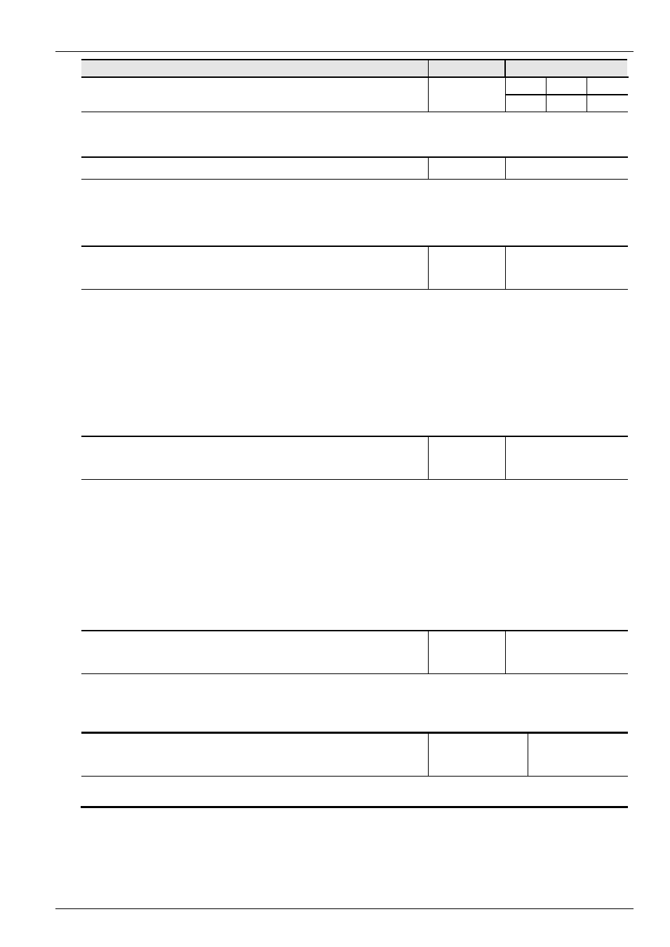
Parameter
Setting value / Description / Note
Parameter set Available with option
P458
Analog output mode
P
MLT
0 ... 1
[ 0 ]
The mode of the analog output of the Multi I/O (SK CU1-MLT, SK CU1-MLT 20mA, optional) is
adjustable.
0 = 0...20mA / 0...10V
1 = 4...20mA / 2...10V
P460
Time watchdog
P
Always visible
0.0 / 0.1 ...
250.0 s
[ 10.0 ]
0.1 ... 250.0 = The time interval between the expected Watchdog signals (programmable function of
the digital inputs P420
– P425). If this time interval elapses without an impulse being registered, a
switch-off and error message E012 are actuated.
0
.0 = Customer error: As soon as a high-low flank or a low signal is detected at a digital input
(function 18) the FI switches off with error message E012.
P480
.. - 01
...
.. - 08
Function Bus I/O In Bits
Always visible
0 ... 48
[ 0 ]
The Bus I/O In Bits are perceived as digital inputs. They can be set to the same functions (P420...425).
[01] =
Bus I/O In Bit 1
[02] =
Bus I/O In Bit 2
[03] =
Bus I/O In Bit 3
[04] =
Bus I/O In Bit 4
[05] =
Bus I/O Initiator 1
[06] = Bus I/O Initiator 2
[07] = Bus I/O Initiator 3
[08] = Bus I/O Initiator 4
The possible functions for the Bus In Bits can be found in the table of functions for the digital inputs
P420...425.
Further details can be found in the manuals for each Bus system.
P481
.. - 01
...
.. - 08
Function Bus I/O Out Bits
Always visible
0 ... 38
[ 0 ]
The bus I/O Out bits are perceived as multi-function relay outputs. They can be set to the same
functions (P434...443).
[01] =
Bus I/O Out Bit 1
[02] =
Bus I/O Out Bit 2
[03] =
Bus I/O Out Bit 3
[04] =
Bus I/O Out Bit 4
[05] =
Bus I/O Actuator 1
[06] = Bus I/O Actuator 2
[07] = Flag 1
[08] = Flag 2
The possible functions for the Bus Out Bits can be found in the table of functions for the relay P434.
Further details can be found in the manuals for each Bus system.
P482
.. - 01
...
.. - 08
Standardisation of bus I/O Out bits
Always visible
-
400 … 400 %
[ 100 ]
Adjustment of the limit values of the relay functions/Bus Out Bits. For a negative value, the output
function will be output negative.
When the limit value is reached and the setting values are positive, the relay contact closes, with
negative setting values the relay contact opens.
P483
.. - 01
...
.. - 08
Hysteresis of bus I/O Out bits
Always visible
1 … 100 %
[ 10 ]
Difference between switch-on and switch-off point to prevent oscillation of the output signal.