NORD Drivesystems BU0750 User Manual
Page 31
3.2 Overview of Technology Units
BU 0750 GB-3311
Subject to technical amendments
31
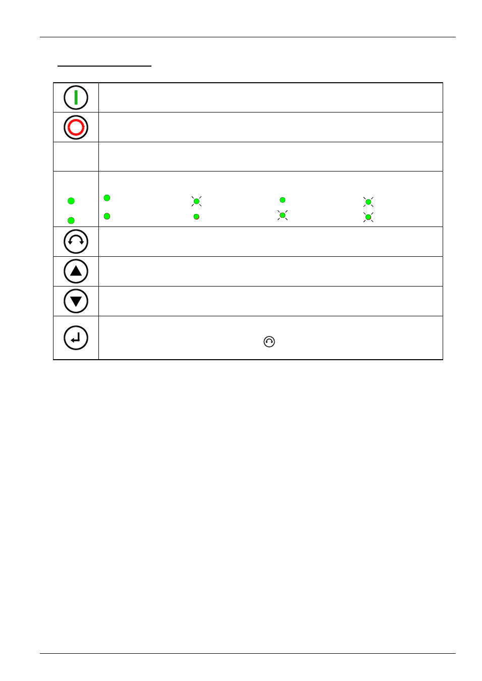
ControlBox functions:
To switch on the frequency inverter. The frequency inverter is now enabled with the set jog frequency
(P113). A preset minimum frequency (P104) may at least be provided.
Parameter >Interface< P509 must = 0.
To switch off the frequency inverter. The output frequency is reduced to the absolute minimum
frequency (P505) and the frequency inverter shuts down.
7-segment
LED
display
Shows the actual operating value set during operation (selection in P001) or an error code. During
parameterisation, the parameter numbers or the parameter values are shown. When switched off, but in
standby mode, four dashes "_ _ _ _" are displayed.
LEDs
1
2
The LEDs indicate the actual operating parameter set in the display and the actual parameter set being
parameterised during parameterisation. In this case the display is coded in binary form.
1
2
= P1
2
1
= P2
1
2
= P3
2
1
= P4
The direction of rotation of the motor changes when this key is pressed. "Rotation to the left" is indicated
by a minus sign. Attention! Take care when operating pumps. screw conveyors, fans, etc. Block the
key with parameter P540.
Press key to increase the frequency. During parameterisation, the parameter number or parameter
value is increased
Press the key to reduce the frequency. During parameterisation, the parameter number or parameter
value is reduced.
Press "ENTER" to store a changed parameter value, or to switch between parameter number or
parameter value.
NOTE: If a changed value is not to be stored, the
key can be used to exit from the parameter
without saving the change.