3 minimum configuration of control connections, P102, P400 – NORD Drivesystems BU0750 User Manual
Page 78: P103, P104, P105, P420, P523
NORDAC SK 750E Manual
78
Subject to technical amendments
BU 0750 GB-3311
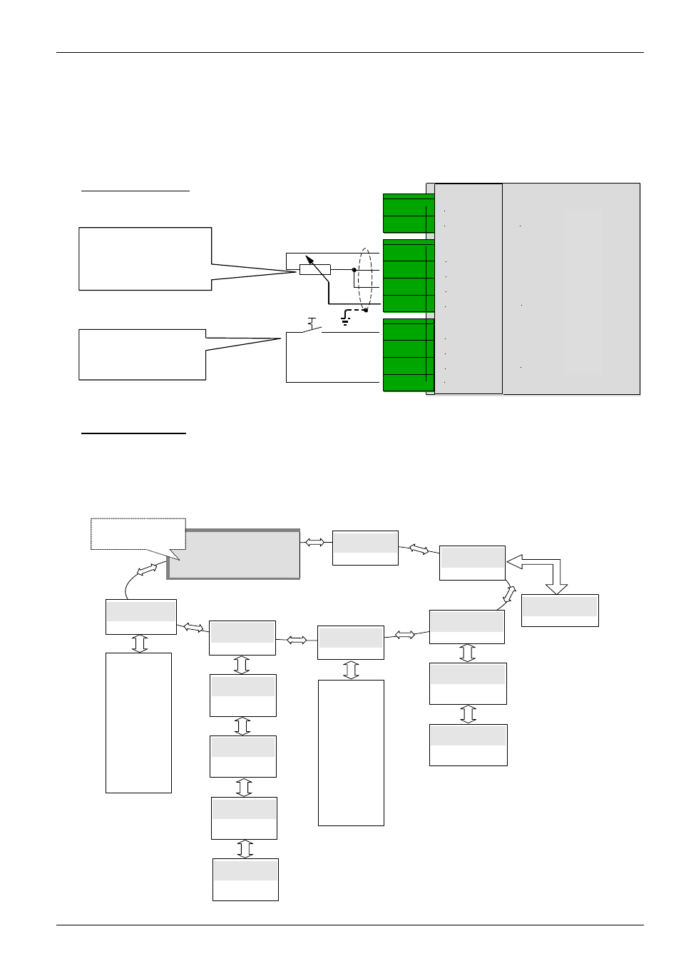
6.3 Minimum configuration of control connections
... with Basic I/O and ControlBox (Option: SK CU1-BSC + SK TU2-CTR)
If the frequency inverter is to be controlled via the digital and analog inputs, this can be implemented
immediately in the delivery condition. Settings are not necessary for the moment.
The prerequisite is the installation of a customer unit, e.g. the Basic I/O (as described here).
Minimum circuitry
Basic parameters
If the present setting of the frequency inverter is not known. loading of the default parameters is
recommendedd P523 = 1. In In this configuration the frequency inverter is parameterised for standard
applications. If necessary, the following parameters can be modified (with the ControlBox option
SK TU2-CTR).
B
a
si
c-
K
u
n
d
e
n
sc
h
n
itt
st
e
lle
X
3
.3
X
3
.2
X
3
.1
01 REL1.1
02 REL1.2
11 VREF 10V
12 AGND /0V
13 AIN1 -
14 AIN1 +
21 DIG IN 1
22 DIG IN 2
23 DIG IN 3
42 VO +15V
Potentiometer, 10kOhm
(Function
= P400)
(Range
= P104/105)
Switch, ON/OFF
(Function
= P420)
B
a
sic cu
st
o
m
e
r un
it
P0 - -
Operating displays
_ _ _ _
P1--
Basic parameters
P2- -
Motor data
P4- -
Control clamps
P5- -
Extra functions
P7- -
Information
As stan
dard
the
act
ual
ou
tput fre
quen
cy
is
dis
pla
yed
P102
Acceleration time
0 ... 320s
Motor da
ta
See
4
.1
D
efa
ult
sett
ings
P400
Function analog input
0...10V -frequency-
Operating values
display (or operational)
following mains ON
P103
Deceleration time
0 ... 320s
P104
Min. frequency
0 ... 400Hz
P105
Max. frequency
0.1 ... 400Hz
P420
Funct. Digital input 1
- ON right -
P523
Load default data