NORD Drivesystems BU0750 User Manual
Page 121
7.9 Information
BU 0750 GB-3311
Subject to technical amendments
121
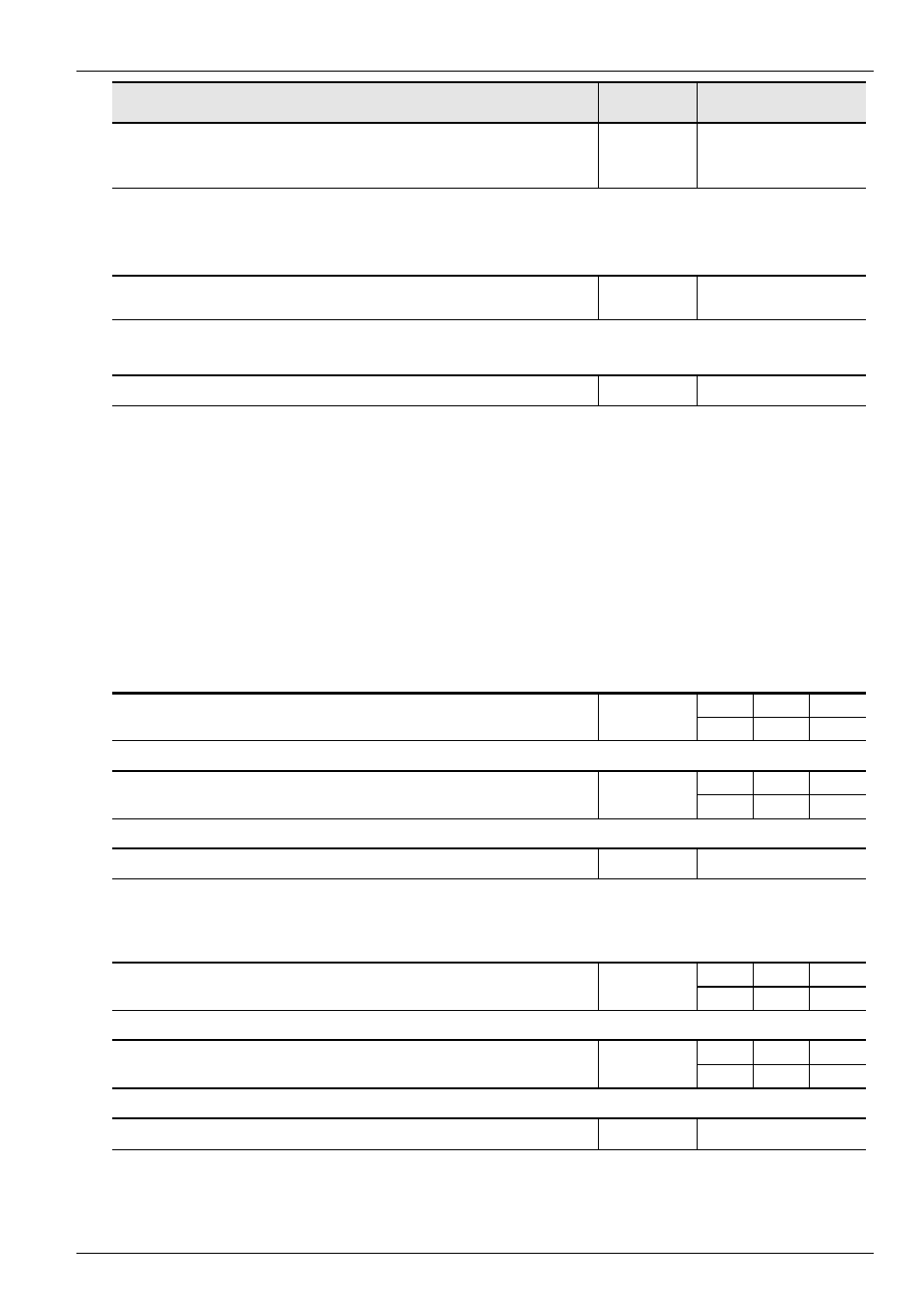
Parameter
Setting value / Description / Note
Parameter
set
Available with option
P706
.. - 01
...
.. - 05
Parameter set, last error 1...5
Always visible
0 ... 3
This parameter stores the parameter set code that was active when the error occurred. Data for
the previous 5 faults are stored.
The ControlBox must be used to select the corresponding memory location 1-5 (Array), and
confirmed using the ENTER key to read the stored error code.
P707
.. - 01
.. - 02
Software version
Always visible
0 ... 9999
This parameter shows the software and revision
numbers in the FI. This can be significant when
different FIs are assigned the same settings.
... - 01 = Version number (3.1)
... - 02 = Revision number (1.0)
P708
Status of digital inputs
Always visible
00 ... 3F
(hexadecimal)
Displays the status of the digital inputs in hexadecimal code. This display can be used to check
the input signals.
Bit 0 = Digital input 1 [far right]
Bit 1 = Digital input 2
Bit 2 = Digital input 3
Bit 3 = Digital input 4
Bit 4 = Digital input 5
Bit 5 = Digital input 6
Bit 6 = Digital input 7 (only with PosiCon)
Bit 7 = Digital input 8 (only with PosiCon)
Bit 8 = Digital input 9 (only with PosiCon)
Bit 9 = Digital input 10 (only with PosiCon)
Bit 10 = Digital input 11 (only with PosiCon)
Bit 11 = Digital input 12 (only with PosiCon)
Bit 12 = Digital input 13 (only with encoder)
ControlBox: If there are only four digital inputs, the status is indicated in binary code. If the
Customer Unit Multi I/O, Encoder or PosiCon is installed (Bit 4, 5 ...), the display
is coded in hexadecimal.
P709
Voltage analog input 1
BSC
STD
MLT
-10.0 ... 10.0 V
Displays the measured analog input value 1. (-10.0 ... 10.0V)
P710
Voltage analog output 1
STD
MLT
0.0 ... 10.0V
Displays the value which is output from analog output 1. (0.0 ... 10.0V)
P711
Status multifunction relay
Always visible
00 ... 11 (binary)
Displays the actual status of the signal relays.
Bit 0 = Relay 1
Bit 1 = Relay 2
Bit 2 = Relay 3 (only with PosiCon option)
Bit 3 = Relay 4 (only with PosiCon option)
P712
Voltage analog input 2
MLT
-10.0 ... 10.0 V
Displays the measured analog input value 2. (-10.0 ... 10.0V)
P713
Voltage analog output 2
MLT
0.0 ... 10.0V
Displays the value which is output from analog output 2. (0.0 ... 10.0V)
P714
Operating time
Always visible
0.0 ... 9999 h
This parameter shows the time for which the FI was connected to the mains and was ready for
operation.