NORD Drivesystems BU0750 User Manual
Page 54
NORDAC SK 750E Manual
54
Subject to technical amendments
BU 0750 GB-3311
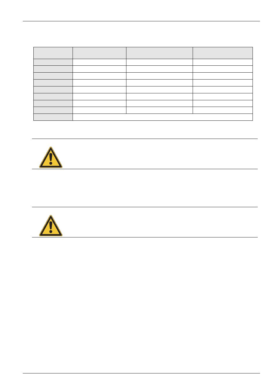
3.6 Colour and contact assignments for the incremental encoders
Function
Cable colours,
for incremental encoder
Assignment for encoder option
SK XU1-ENC
Assignment for encoder option
SK XU1-POS
15 V supply
brown / green
X11.1.42 VO +15V
X10.2.42 VO +15V
0 V supply
white / green
X11.1.40 GND /0V
X10.4.40 GND /0V
Track A
brown
X11.2.51 ENC1 A+
X10.4.51 ENC1 A+
Track A inverse
green
X11.2.52 ENC1 A-
X10.4.52 ENC1 A-
Track B
grey
X11.2.53 ENC1 B+
X10.4.53 ENC1 B+
Track B inverse
pink
X11.2.54 ENC1 B-
X10.4.54 ENC1 B-
Track 0
red
--
X10.4.55 ENC1 N+
Track 0 inverse
black
--
X10.4.56 ENC1 N-
Cable shield
connected to a large area of the frequency inverter housing or shielding angle
NOTE
If there are deviations from the standard equipment (A.772.4) for the motors, please note the
accompanying data sheet or consult your supplier.
RECOMMENDATION: For greater reliability, in particular with long connection cables, we recommend the use of a higher
power supply (15V/24V) and an incremental encoder for 10-30V power supply. The signal level must
still be 5V TTL.
ATTENTION
The rotation field of the incremental encoder must correspond to that of the motor. Because of
this, according to how the encoder is mounted on the motor (possible mirror image), tracks A+
and A- may need to be switched over or a negative sign entered in parameter P301. For
SK 750E, inverted mounting has already been taken into account!