7 extra functions, P503 master function output, P504 pulse frequency – NORD Drivesystems BU0750 User Manual
Page 109
BU 0750 GB-3311
Subject to technical amendments
109
7.7 Extra functions
Parameter
Setting value / Description / Note
Parameter
set
Available with option
P503
Master function output
Always visible
0 ... 8
[ 0 ]
To use the Master function output, the inverter controller source must be selected in P509. Only the
master frequency (setpoint 1 and control word) is transferred with Mode 1, while the actual values
selected in P543, P544 and P545 are transferred in Mode 2.
In Mode 3 a 32Bit actual position and a 16Bit setpoint speed (after ramp) is output. Mode 3 is
required for synchronous control with the POSICON option.
Mode 4 = Curve control. Please refer to the detailed supplementary documentation. The first word
which is transmitted: status word, 2nd word: actual setpoint frequency before the speed ramp, 3rd
word: actual torque current standardised to the torque limit, 4th word: present actual frequency (with
slip frequency removed)
0 = Off
1 = USS Mode 1 (Freq.)
2 = CAN Mode 1 (Freq.)
up to 250kBaud
3 = USS Mode 2
(IW 1-3)
4 = CAN Mode 2
(IW 1-3)
up to 250kBaud
5 = USS Mode 3
(GL)
6 = CAN Mode 3
(GL)
7 = USS Mode 4
(KS)
8 = CAN Mode 4
(KS)
P504
Pulse frequency
Always visible
3.0 ... 16.0 kHz
[ 6.0 ]
The internal pulse frequency for controlling the power component can be changed with this
parameter. A high set value results in less noise from the motor, but also to higher EMC radiation.
Note:
The degree of interference suppression for limit curve A as per EN 55011 is complied
with using a setting of 6kHz, on condition that the wiring guidelines are complied with.
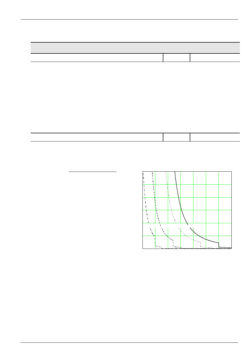
I
2
t FI characteristic curve,
an increase of the pulse
frequency
results
in
a
reduction of the output
current depending on time.
t sec
(
)
0.8
1
1.2
1.4
1.6
1.8
2
2.2
0
30
60
90
120
150
180
20 kHz
16 kHz
10 kHz
<=6kHz
x Inenn
x I
nom