Glc-9000 user manual, Warning indicator – GW Instek GLC-9000 User Manual User Manual
Page 32
GLC-9000 User Manual
32
5. Warning
Indicator
GLC-9000
The warning indicator lights up
when high voltages are produced
from terminals T1, T2 or T3. The
warning indicator will flash when
in standby mode.
6. Measuring
Terminals
250V T32mA
25mA
250V
25mA
T2
25V
CAT
II
T1
LEAKAGE CURRENT
Measuring Terminals T1 and T2 are
used to measure leakage current.
Terminal T2 has a replaceable fuse
(250V, 32mA), see page 181 for
details.
7. Circuit
Breaker
GLC-9000
The circuit breaker has over-current
protection for the EUT rated at 15A.
When testing, the warning indicator
will illuminate.
I: ON, normal operation
O: OFF, inactive or during over-
current protection.
8. EUT AC
Terminal
Block
GLC-9000
Supplies AC power for the EUT.
Includes automatic shut-down
(circuit breaker) with over-current
protection. Maximum current
output 10A, maximum power
output, 1500VA.
Note: The Live (L) and Neutral (N)
line inputs are user-defined. Please
see page 108 to configure the L and
N line inputs.
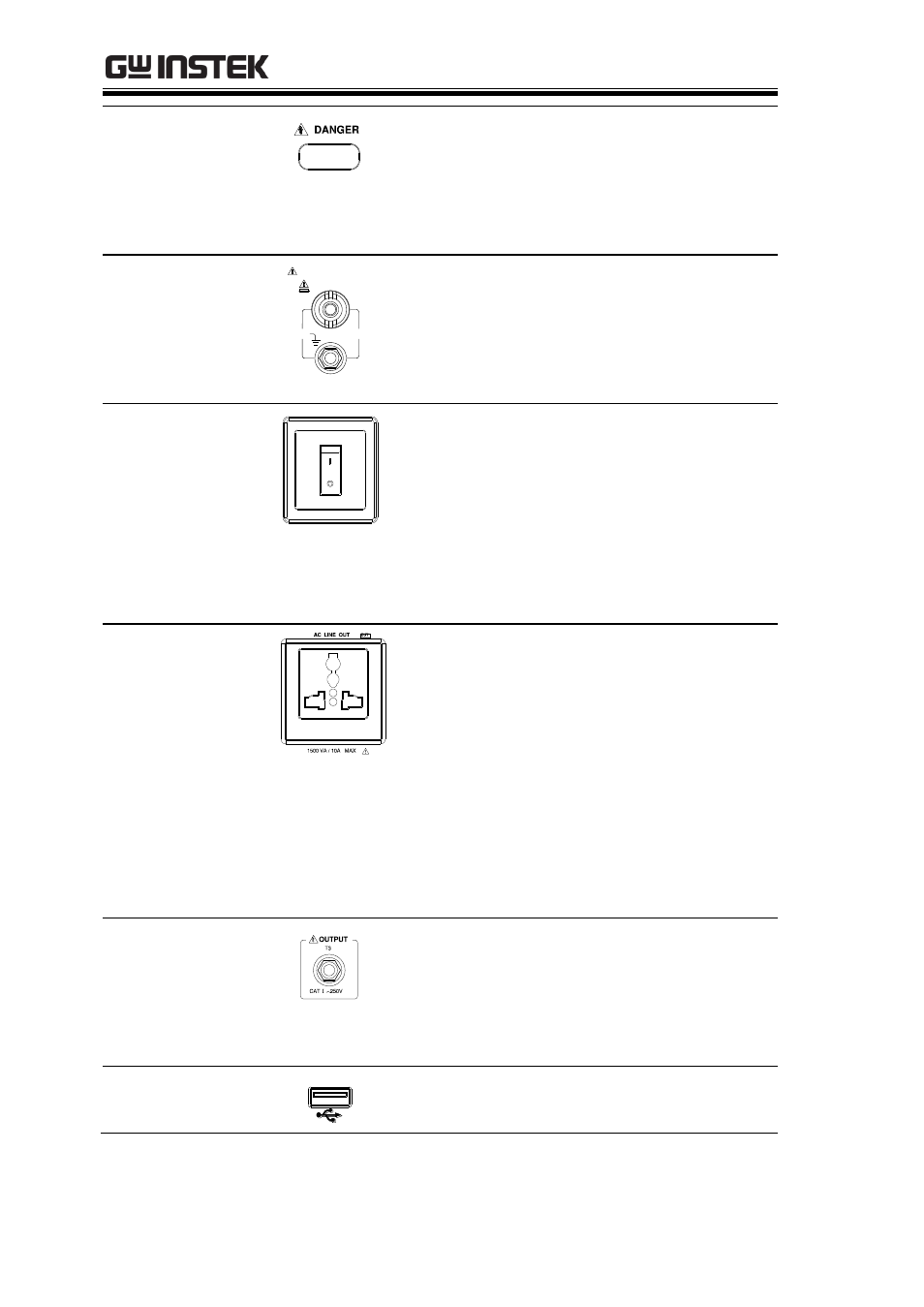
9. T3 110%
Voltage
Application
GLC-9000
An isolated voltage (1:1) is output to
T3 from the EUT AC IN voltage by
an isolation transformer. This
terminal is limited to medical
networks (MD:F)
10. USB HOST
GLC-9000
USB host terminal. For more details
see the Remote chapter on page 111.