Yokogawa, Fm/csa control drawing rotamass rcct3 – Yokogawa RotaMASS 3-Series User Manual
Page 90
9. EXPLOSION PrOTECTEd TyPE INSTrUMENTS
9-14
IM 01R04B05-00E-E 3rd edition July 30, 2010 -00
all Rights Reserved. Copyright © 2005, Rota Yokogawa
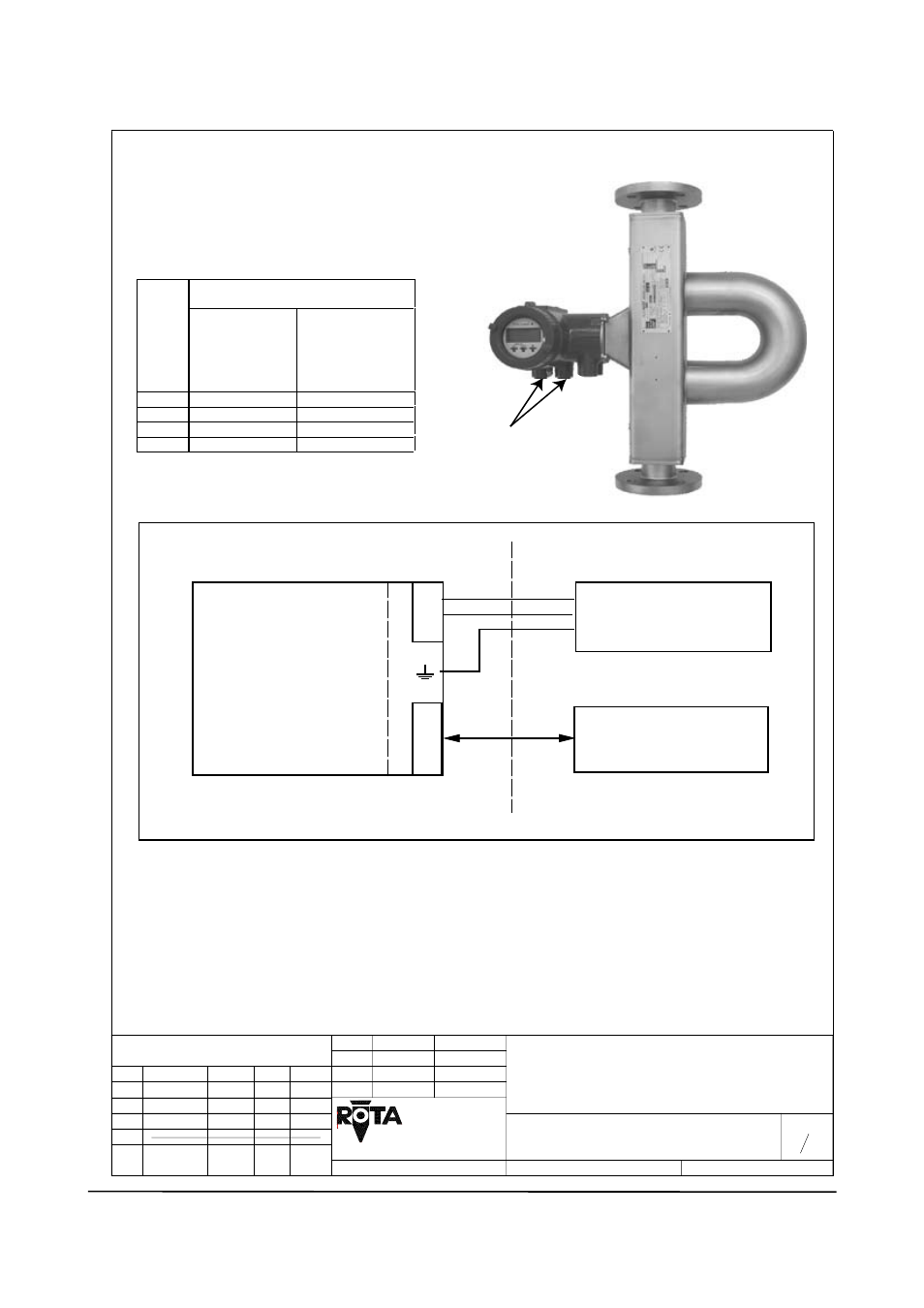
9.2.5 Control drawings
1 1
8300026
FM/CSA CONTROL DRAWING
ROTAMASS RCCT3
Butz
09.02.2005
09.02.2005 Rü
L/+
N/-
G
CKECKED
DRAWED
UPDATE No.
Rev.
a
DATE
EDITOR CHECKED
TITEL:
79664 WEHR
YOKOGAWA
NAME
DATE
DWG. No.:
RCCT34 to RCCT39/XR
Temp.
class
T6
≤ 50°C / 122°F
≤ 65°C / 149°F
T5
≤ 50°C / 122°F
≤ 80°C / 176°F
T4
≤ 50°C / 122°F
≤ 115°C / 239°F
T3
≤ 50°C / 122°F
≤ 150°C / 302°F
NPT 1/2"
Hazardous Locations :
Class I Division 1 Groups A,B,C,D or Class I Zone 1 Group IIC
Class I Division 1 Groups C,D or Class I Zone 1 Group IIB (option /HP)
and Class II and III Division 1 Groups E,F,G
The minimum ambient temperature is -40°C / -40°F
WARNING : Substitution of components may impair intrinsic safety.
Note :
-
For AC-version maximum power supply is 250V AC.
-
For DC-version maximum power supply is 28.8V DC.
-
The installation must be in accordance with the national electrical code, NFPA70, article 504 to 510
and ANSI/ISA RP 12.06.01.
-
The non intrinsically safe terminals must not be connected to any device that uses or generates more
than 250Vrms or dc unless it has been determined that the voltage was adequately isolated.
-
Installation must be in accordance with the Canadian Electrical Code, when installed in Canada.
Max.
Medium
temperature or
temperature of
heat carrier
Max.
Ambient
temperature
Power supply
I/O control
HAZARDOUS LOCATION
NON HAZARDOUS LOCATION
I/O
Rotamass RCCT3
GERMANY
b ---------- 1.9.05 Butz Rü
c ---------- 5.3.07 Butz Rü
Temperature classification :
Installation :