4 setting of tags and addresses – Yokogawa RotaMASS 3-Series User Manual
Page 27
5. CONFIGUrATION
5-3
IM 01R04B05-00E-E 3rd edition July 30 2010 -00
all Rights Reserved. Copyright © 2005, Rota Yokogawa
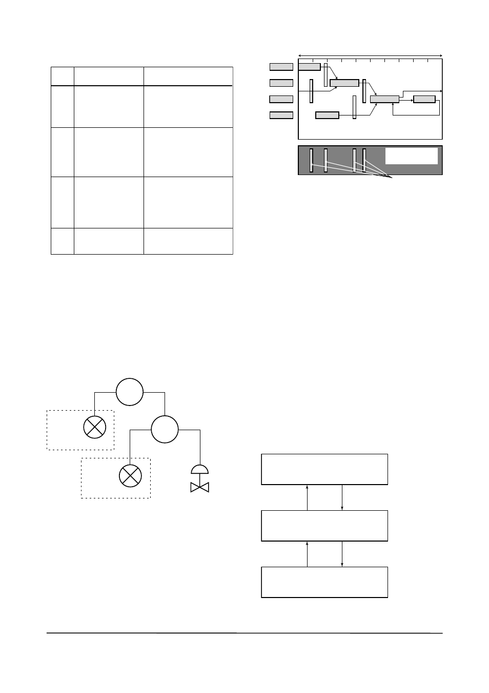
Table 5.3 Function Block Execution Schedule
of rOTAMASS
t0503.EPS
Index
Parameters
Setting (Factory Setting in
Parentheses)
269
(SM)
MaCRoCYCLE_DuRatIon Repetition period of control
or measurement, i.e.,
macrocycle; to be set as a
multiple of 1/32 ms (32000 =
1 second)
276
(SM)
FB_StaRt_EntRY.1 Start time of the aI1 block
represented as the elapsed
time from the start of each
macrocycle; to be set as a
multiple of 1/32 ms (0 = 0
ms)
277
(SM)
FB_StaRt_EntRY.2 Start time of the PID block
(optional) represented as
the elapsed time from the
start of each macrocycle; to
be set as a multiple of 1/32
ms (9600 = 300 ms)
278 (SM)
to
289 (SM)
FB_StaRt_EntRY.3 to
FB_StaRt_EntRY.14
not set.
a maximum of 30 ms is taken for execution
of each aI block. arrange the communication
schedule for an aI block’s data that is to be trans-
ferred to its downstream block in such a way that
it starts after a lapse of longer than 30 ms.
Figure 5.3 shows typical function block and com-
munication schedules for the loop shown in Figure
5.2.
F0502.EPS
FIC100
FIC200
FC100
FI200
ROTAMASS
#2
FI100
ROTAMASS
#1
Figure 5.2 Example of Loop Connecting Func-
tion Blocks of two rOTAMASS with other
devices
FI103
FI100
FC100
FIC100
FC200
FIC200
FC100
FI200
FI200
Function
Block
Schedule
Commu-
nication
Schedule
OUT
IN
OUT
CAS_IN
BKCAL_OUT
BKCAL_IN
BKCAL_IN
BKCAL_OUT
IN
Unscheduled
Communication
Scheduled
Communication
F0503.EPS
Macrocycle (Control Period)
Figure 5.3 Function Block Schedule and
Communication Schedule
When the control period (macro cycle) is set to
more than 4 seconds, set the following interval to
be more than 1% of the control period.
- Interval between “end of block execution” and
“start of sending CD from LaS”
- Interval between “end of block execution” and
“start of the next block execution”
5.4 Setting of Tags and
Addresses
this section describes the steps in the proce-
dure to set the PD tags and node address in the
RotaMaSS. there are three states of Fieldbus
devices as shown in Figure 5.4, and if the state is
other than the lowest SM_oPERatIonaL state,
no function block is executed. Whenever you have
changed the PD tag or address of a RotaMaSS,
transfer its state to SM_oPERatIonaL.
unInItIaLIZED
(no tag nor address is set)
tag clear
tag setting
InItIaLIZED
(only tag is set)
SM_oPERatIonaL
(tag and address are retained, and
the function block can be executed.)
address clear
F0504.EPS
address setting
Figure 5.4 Status Transition by Setting Pd
Tag and Node Address