Getting started, 1 connection of devices – Yokogawa RotaMASS 3-Series User Manual
Page 21
4. GETTING STArTEd
4-1
IM 01R04B05-00E-E 3rd editionJuly 30, 2010-00
all Rights Reserved. Copyright © 2005, Rota Yokogawa
4. GETTING STArTEd
Fieldbus is fully dependent upon digital communi-
cation protocol and differs in operation from con-
ventional 4 to 20 ma transmission and the HaRt
communication protocol. It is recommended that
novice users use fieldbus devices in accordance
with the procedures described in this section. the
procedures assume that fieldbus devices will be
set up on a bench of an instrument shop.
4.1 Connection of devices
the following instruments are required for use
with Fieldbus devices:
• Fieldbus Communication Signal:
Fieldbus requires a dedicated power supply. It
is recommended that current capacity be well
over the total value of the maximum current
consumed by all devices (including the host).
Conventional DC current cannot be used as is.
• Terminator:
Fieldbus requires two terminators. Refer to the
supplier for details of terminators that are
attached to the host.
• Field devices:
Connect your Fieldbus communication type
RotaMaSS RCCt3 to a fieldbus. two or
more RotaMaSS RCCt3 and other field
devices can be connected. For the terminal
assignment on the RotaMaSS RCCt3, see
table 4.1.
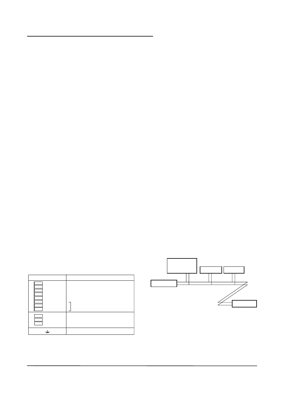
Table 4.1 Terminal Connection for rOTAMASS rCCT3
terminal Symbols
Description
Fieldbus communication signal
Ground terminal
F0401.EPS
+
–
n.C.
n.C.
n.C.
n.C.
n.C.
n.C.
FF out
FF out
L/+
n/-
G
Power supply
• Host:
used for accessing field devices. a dedicated
host (such as DCS) is used for an instrumen-
tation line while dedicated communication
tools are used for experimental purposes. For
operation of the host, refer to the instruction
manual for each host. no details of the host
are explained in the rest of this manual.
• Cable:
used for connecting devices. Refer to “Field-
bus technical Information” (tI 38K3a01-01E)
for details of instrumentation cabling. If the
total length of the cable is in a range of 2 to
3 meters for laboratory or other experimental
use, the following simplified cable (a twisted
pair wire with a cross section of 0.9 mm
2
or
more and cycle period of within 5 cm
2 inches
may be used). termination processing de-
pends on the type of device being deployed.
For the RotaMaSS, clamp terminal are used.
Some hosts require a connector.
Refer to Yokogawa when making arrangements to
purchase the recommended equipment.
Connect the devices as shown in Figure 4.1.
Connect the terminators at both ends of the trunk,
with a minimum length of the spur laid for connec-
tion.
the polarity of signal and power must be main-
tained.
Fieldbus power
supply
terminator
terminator
HoSt
F0402.EPS
RotaMaSS
Figure 4.1 device Connection
Before using a Fieldbus configuration tool other
than the existing host, confirm it does not affect
the loop functionality in which all devices are
already installed in operation. Disconnect the rel-
evant control loop from the bus if necessary.