A5.3 parameters of pid block, A-48 – Yokogawa RotaMASS 3-Series User Manual
Page 148
APPENdIX 5. PId BLOCK
a-48
IM 01R04B05-00E-E 3rd edition July 30, 2010 -00
all Rights Reserved. Copyright © 2005, Rota Yokogawa
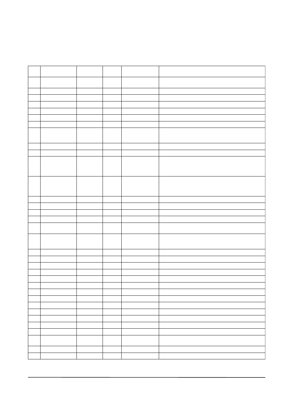
A5.3 Parameters of PId Block
notE: In the table below, the
Write column shows the modes in which the respective parameters can
be written. a blank in the Write column indicates that the corresponding parameter can be written in all
modes of the PID block. a dash (–) indicates that the corresponding parameter cannot be written in any
mode.
0
1
2
3
4
5
6
7
8
9
10
11
12
13
14
15
16
17
18
19
20
21
22
23
24
25
26
27
28
29
30
31
32
33
Index
Default
(factory setting)
Parameter
name
Valid Range
Write
Description
Block Header
St_REV
taG_DESC
StRatEGY
aLERt_KEY
MoDE_BLK
BLoCK_ERR
PV
SP
out
PV_SCaLE
out_SCaLE
GRant_DEnY
ContRoL_oPtS
StatuS_oPtS
In
PV_FtIME
BYPaSS
CaS_In
SP_RatE_Dn
SP_RatE_uP
SP_HI_LIM
SP_Lo_LIM
GaIn
RESEt
BaL_tIME
RatE
BKCaL_In
out_HI_LIM
out_Lo_LIM
BKCaL_HYS
BKCaL_out
RCaS_In
Rout_In
taG: “PID”
(blank)
0
1
0
100
0
1342 (%)
1
100
0
1342 (%)
1
0
0
0
0
0sec
1 (off)
0
1.#InF
1)
1.#InF
1)
100
0
1
10
0
0
0
100
0
0.5 (%)
0
0
0
Block tag
= o/S
---
---
---
auto
Man
o/S
o/S
auto
o/S
o/S
auto
Man
---
Same as that for an aI block.
Same as that for an aI block.
Same as that for an aI block.
Same as that for an aI block.
Same as that for an aI block.
Same as that for an aI block.
Measured value; the non-dimensional value that is
converted from the input (In) value based on the
PV_SCaLE values and filtered.
Setpoint
output
upper and lower scale limit values used for scaling of the
input (In) value.
upper and lower scale limit values used for scaling of the
control output (out) value to the values in the
engineering unit.
Same as that for an aI block.
Setting for control action. See Section a5.13 for details.
See Section a5.15 for details.
Controlled-value input
time constant (in seconds) of the first-order lag filter
applied to In
Whether to bypass the control computation.
1 (off): Do not bypass.
2 (on): Bypass.
Cascade setpoint
Rate-of-decrease limit for setpoint (SP)
Rate-of-increase limit for setpoint (SP)
upper limit for setpoint (SP)
Lower limit for setpoint (SP)
Proportional gain (= 100 / proportional band)
Integration time (seconds)
unused
Derivative time (seconds)
Read-back of control output
upper limit for control output (out)
Lower limit for control output (out)
Hysteresis for release from a limit for out.status
Read-back value to be sent to the BKCaL_In in the
upper block
Remote setpoint set from a computer, etc.
Remote control output value set from a computer, etc.
1 to 255
PV_SCaLE 10%
non-negative
1, 2
Positive
Positive
PV_SCaLE 10%
PV_SCaLE 10%
Positive
Positive
out_SCaLE 10%
out_SCaLE 10%
0 to 50%
ta0502-1.EPS
1)
Initial value: all limits are set to plus or minus infinity (+InF or -InF), which is the same as no limit. IEEE 754-1985
defines the floating point representation of plus and minus infinity.