Yokogawa RotaMASS 3-Series User Manual
Page 107
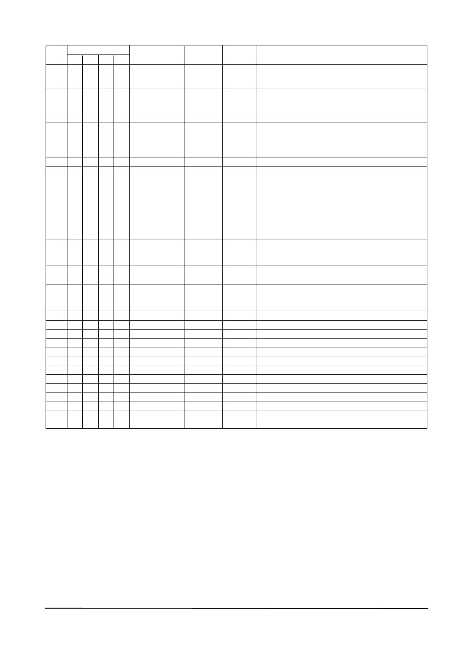
APPENdIX 1. LIST OF PArAMETErS FOr EACH BLOCK OF rOTAMASS
a-7
IM 01R04B05-00E-E 3rd edition July 30, 2010 -00
all Rights Reserved. Copyright © 2005, Rota Yokogawa
TA0102-4.EPS
1)
Initial value: All limits are set to plus or minus infinity (+INF or -INF), which is the same as no limit. IEEE 754-1985 defines the
floating point representation of plus and minus infinity.
AUTO
Rel.
Index
Index
Parameter Name
Factory
Default
Write
Mode
Explanation
AUTO
AUTO
AUTO
AUTO
17
18
19
20
21
22
23
24
25
26
27
28
29
30
31
32
—
0.0 (AI5)
0.0 (AI6)
0
—
—
0
—
AUTO
LOW_CUT
PV_FTIME
0
HI_HI_LIM
FIELD_VAL
UPDATE_EVT
BLOCK_ALM
ALARM_SUM
ACK_OPTION
ALARM_HYS
HI_HI_PRI
HI_PRI
HI_LIM
LO_PRI
LO_LIM
LO_LO_PRI
1. #INF
1)
AUTO
0xffff
0.5%
33
LO_LO_LIM
HI_HI_ALM
AUTO
AI5 AI6
Raw value of the field device in percent of thePV range,
with a status reflecting the Transducer condition, before
signal characterization (L_TYPE), filtering (PV_FTIME), or
low cut (LOW_CUT).
The block alarm is used for all configuration, hardware,
connection failure or system problems in the block. The
cause of the alert is entered in the subcode field. The first
alert to become active will set the Active status in the
Status attribute. As soon as the Unreported status is
cleared by the alert reporting task, another block alert may
be reported without clearing the Active status, if the
subcode has changed.
The current alert status, unacknowledged states,
unreported states, and disabled states of the alarms
associated with the function block.
Selection of whether alarms associated with the block will
be automatically acknowledged.
Amount the PV must return within the alarm limits before
the alarm condition clears. Alarm Hysteresis is expressed
as a percent of the PV span. 0 to 50
Priority of the high high alarm. 0, 1, 3 to 15
Priority of the high alarm. 0, 1, 3 to 15
The setting for high alarm in engineering units.
Priority of the low alarm. 0, 1, 3 to 15
The setting for the low alarm in engineering units.
Priority of the low low alarm. 0, 1, 3 to 15
The setting of the low low alarm in engineering units
.
The status for high high alarm and its associated time stamp
.
The status for high alarm and its associated time stamp
.
The status of the low alarm and its associated time stamp
.
The status of the low low alarm and its associated time
stamp.
This alert is generated by any change to the static data
.
Sets low cut point of output. This low cut value become
available by setting "Low cutoff" to "IO-OPTS".
Time constant of a single exponential filter for the PV, in
seconds.
The setting for high high alarm in engineering units.
—
—
—
—
AUTO
0
AUTO
AUTO
34
HI_ALM
35
LO_ALM
36
LO_LO_ALM
1. #INF
1)
-1. #INF
1)
0
-1. #INF
1)
AUTO
—
—
—
—
4417
4418
4419
4420
4421
4422
4423
4424
4425
4426
4427
4428
4429
4430
4431
4432
4433
4434
4435
4436
4517
4518
4519
4520
4521
4522
4523
4524
4525
4526
4527
4528
4529
4530
4531
4532
4533
4534
4535
4536