A-49 – Yokogawa RotaMASS 3-Series User Manual
Page 149
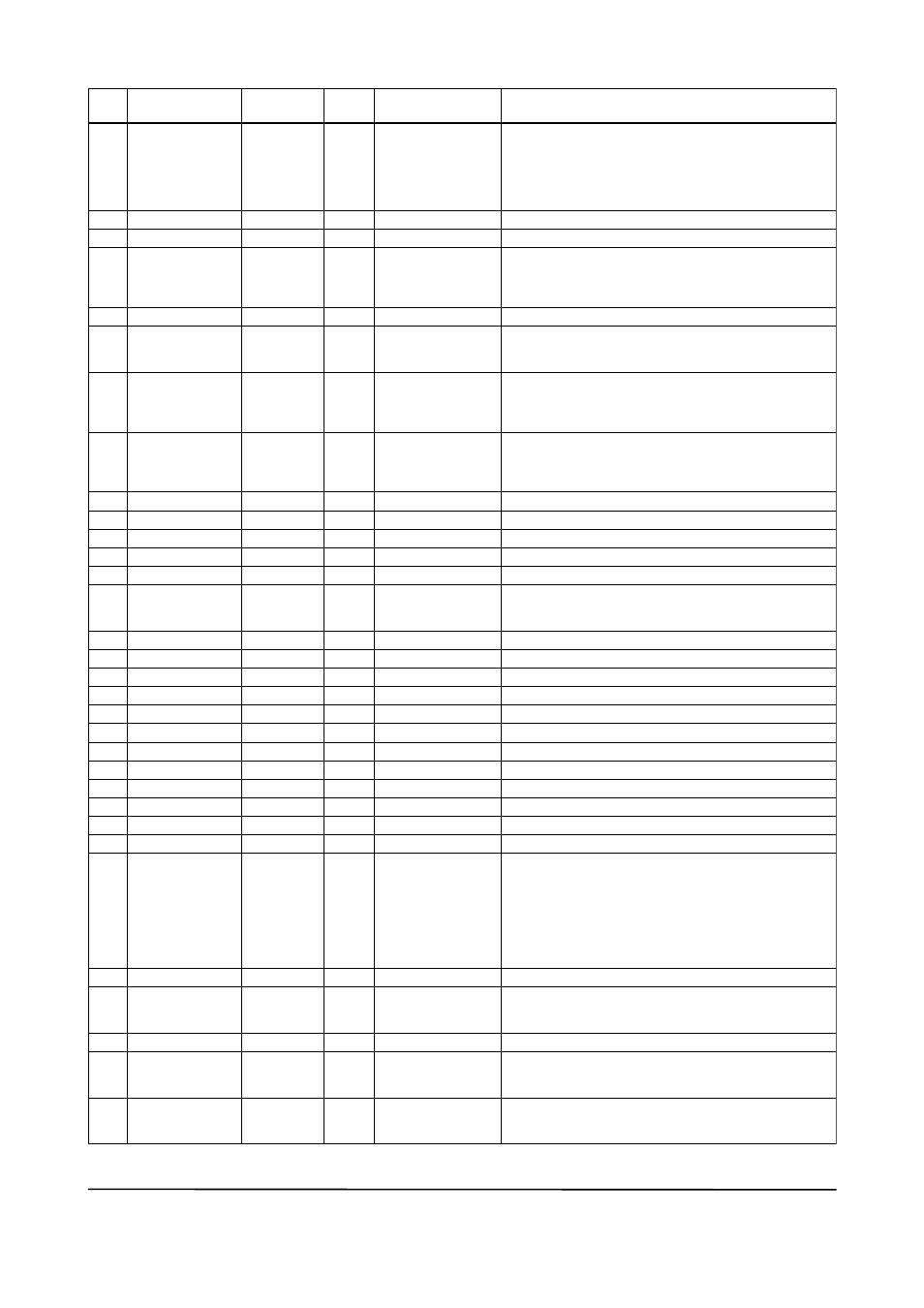
APPENdIX 5. PId BLOCK
a-49
IM 01R04B05-00E-E 3rd edition July 30, 2010 -00
all Rights Reserved. Copyright © 2005, Rota Yokogawa
34
35
36
37
38
39
40
41
42
43
44
45
46
47
48
49
50
51
52
53
54
55
56
57
58
59
60
61
62
63
64
65
Index
Default
(factory setting)
Parameter
name
Valid Range
Write
Description
SHED_oPt
RCaS_out
Rout_out
tRK_SCaLE
tRK_In_D
tRK_VaL
FF_VaL
FF_SCaLE
FF_GaIn
uPDatE_EVt
BLoCK_aLM
aLaRM_SuM
aCK_oPtIon
aLaRM_HYS
HI_HI_PRI
HI_HI_LIM
HI_PRI
HI_LIM
Lo_PRI
Lo_LIM
Lo_Lo_PRI
Lo_Lo_LIM
DV_HI_PRI
DV_HI_LIM
DV_Lo_PRI
DV_Lo_LIM
HI_HI_aLM
HI_aLM
Lo_aLM
Lo_Lo_aLM
DV_HI_aLM
DV_Lo_aLM
0
0
0
100
0
1342
1
0
0
0
100
0
1342
1
0
Enable
0
0.5%
0
1. #InF
1)
0
1. #InF
1)
0
-1. #InF
1)
0
-1. #InF
1)
0
1. #InF
1)
0
-1. #InF
1)
---
---
---
---
---
---
---
---
Man
Man
Man
---
---
---
---
---
---
---
---
action to be performed in the event of mode shedding.
SHED_oPt defines the changes to be made to
MoDE.BLK.target and MoDE.BLK.actual when the value
of RCaS_In.status or Rout_In.status becomes Bad if
MoDE_BLK.actual = RCas or Rout.
See Section a5.17.1 for details.
Remote setpoint sent to a computer, etc.
Remote control output value
upper and lower scale limits used to convert the output
tracking value (tRK_VaL) to non-dimensional.
Switch for output tracking. See Section a5.12 for details.
output tracking value (tRK_VaL)
When MoDE_BLK.actual = Lo, the value scaled from the
tRK_VaL value is set in out.
Feedforward input value.
the FF_VaL value is scaled to a value with the same
scale as for out, multiplied by the FF_GaIn value, and
then added to the output of the PID computation.
Scale limits used for converting the FF_VaL value to a
non-dimensional value.
Gain for FF_VaL
Same as that for an aI block.
Same as that for an aI block.
Same as that for an aI block.
Same as that for an aI block.
Hysteresis for alarm detection and resetting to prevent
each alarm from occurring and recovering repeatedly
within a short time.
Priority order of HI_HI_aLM alarm
Setting for HI_HI_aLM alarm
Priority order of HI_aLM alarm
Setting for HI_aLM alarm
Priority order of Lo_aLM alarm
Setting for Lo_aLM alarm
Priority order of Lo_Lo_aLM alarm
Setting for Lo_Lo_aLM alarm
Priority order of DV_HI_aLM alarm
Setting for DV_HI_aLM alarm
Priority order of DV_Lo_aLM alarm
Setting for DV_Lo_aLM alarm
alarm that is generated when the PV value has exceeded
the HI_HI_LIM value and whose priority order* is defined
in HI_HI_PRI.
* Priority order: only one alarm is generated at a time.
When two or more alarms occur at the same time, the
alarm having the highest priority order is generated.
When the PV value has decreased below [HI_HI_LIM –
aLM_HYS], HI_HI_aLM is reset.
as above
as above
Reset when the PV value has increased above
[Lo_LIM + aLM_HYS].
as above
alarm that is generated when the value of [PV - SP] has
exceeded the DV_HI_LIM value. other features are the
same as HI_HI_aLM.
alarm that is generated when the value of [PV - SP] has
decreased below the DV_Lo_LIM value. other features
are the same as Lo_Lo_aLM.
0 to 50%
0 to 15
PV_SCaLE
0 to 15
PV_SCaLE
0 to 15
PV_SCaLE
0 to 15
PV_SCaLE
0 to 15
0 to 15
ta0502-2.EPS
1)
Initial value: all limits are set to plus or minus infinity (+InF or -InF), which is the same as no limit. IEEE 754-1985
defines the floating point representation of plus and minus infinity.