A1.3 transducer block – Yokogawa RotaMASS 3-Series User Manual
Page 108
APPENdIX 1. LIST OF PArAMETErS FOr EACH BLOCK OF rOTAMASS
a-8
IM 01R04B05-00E-E 3rd edition July 30, 2010 -00
all Rights Reserved. Copyright © 2005, Rota Yokogawa
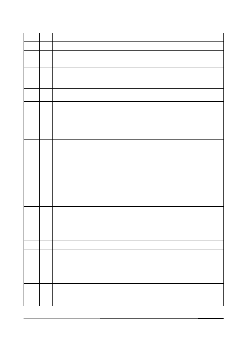
A1.3 Transducer Block
relative
Index
Index
Parameter Name
Factory default
Write
Mode
Explanation
0
2000
Block Header
tag: tB
Block
tag=o/S
Information on this block such as Block tag,
DD Revision, Execution time etc.
1
2001
St_REV
-
the revision level of the static data associated
with the function block. the revision value
will be incremented each time a static
parameter value in the block is changed.
2
2002
taG_DESC
(Spaces)
auto
the user description of the intended appli-
cation of the block
3
2003
StRatEGY
1
auto
the strategy field can be used to identify
grouping of blocks. this data is not checked
or processed by the block.
4
2004
aLERt_KEY
1
auto
the identification number of the plant unit.
this information may be used in the host for
sorting alarms, etc.
5
2005
MoDE_BLK
auto
auto
the actual, target, permitted, and normal
modes of the block.
6
2006
BLoCK_ERR
0
-
this parameter reflects the error status as-
sociated with hardware or software
components associated with a block. It is
a bit string, so that multiple errors may be
shown.
7
2007
uPDatE_EVt
-
this alert is generated by any change to the
static data
8
2008
BLoCK_aLM
-
the block alarm is used for all configura-
tion, hardware, connection failure or system
problems in the block. the cause of the
alert is entered in the sub-code field. the
first alert to become active will set the active
status in the Status attribute.
9
2009
tRanSDuCER_DIRECtoRY
1,2010
-
a directory that specifies the number and
starting indices of the device.
10
2010
tRanSDuCER_tYPE
Standard flow
with calibration
(104)
-
Identifies the device type, which is “Stand-
ard Flow with Calibration” for the Rotamass.
11
2011
XD_ERRoR
0 (no Error)
-
Indicates the error code of the error of the
highest priority from among the errors
currently occurring in the transducer block.
0=no failure, Range 127 (CPu-failure) to
100 (autozero out of Range)
12
2012
CoLLECtIon_DIRECtoRY
-
a directory that specifies the number, start-
ing indices, and DD Item IDS of the data
collections in each transducer within a
transducer block.
13
2013
CaL_PoInt_HI
*)
o/S
the highest calibrated value. to set within
the range of SEnSoR_RanGE.
14
2014
CaL_PoInt_Lo
0
o/S
the lowest calibrated value. to set within
the range of SEnSoR_RanGE.
15
2015
CaL_MIn_SPan
1500
-
the minimum calibration span value allowed.
10% of SEnSoR_RanGE.
16
2016
CaL_unIt
kg/h
-
the engineering unit for the calibrated
sensor.
17
2017
SEnSoR_tYPE
Coriolis (101)
-
Indicates the sensor type, which is “Coriolis”
for the Rotamass.
18
2018
SEnSoR_RanGE
*)
-
the high and low range limits values,
engineering units code and the number of
digits to the right of the decimal point for the
sensor.
19
2019
SEnSoR_Sn
Serial no.
-
the serial number of the connected sensor.
20
2020
SEnSoR_CaL_MEtHoD
Dynamic weigh
(102)
o/S
the method of the last sensor calibration
21
2021
SEnSoR_CaL_LoC
YoKoGaWa
o/S
Sets/indicates the location of the last sensor
calibration.
*) Depends on detector size. For RCCF31 not combined with detector, data for RCCS36 are stored.