3 logical structure of each block, 4 wiring system confi- guration – Yokogawa RotaMASS 3-Series User Manual
Page 20
3. ABOUT FIELdBUS
3-2
IM 01R04B05-00E-E 3rd edition July 30, 2010-00
all Rights Reserved. Copyright © 2005, Rota Yokogawa
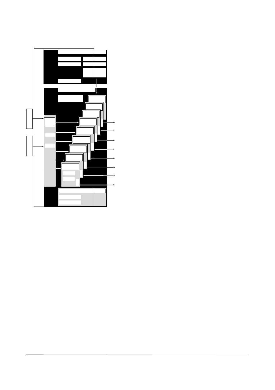
3.3 Logical Structure of
Each Block
F0301.EPS
Rotamass
System/network management VFD
Function block VFD
PD tag
Resource block
Block tag
Parameters
Communication parameters
VCR
Link master
Function block
execution schedule
Temp. sensor
PID function block
(optional)
IT 2 Integrator
block
IT 1 Integrator
block
OUT
AI5 function
block
OUT
AI6 function
block
Node address
Sensor
input
Sensor Coils
Output
OUT
OUT
Sensor
input
Block tag
Parameters
Transducer
block
Software download
function
(optional)
AI4 function
block
OUT
AI3 function
block
OUT
AI2 function
block
OUT
AI1 function
block
Block tag
Parameters
OUT
Figure 3.1 Logical Structure of Each Block
Various parameters, the node address, and the
PD tag shown in Figure 3.1 must be set before
using the device. Refer to Chapter 4 for the set-
ting procedures.
3.4 Wiring System Confi-
guration
the number of devices that can be connected to
a single bus and the cable length vary depending
on system design. When constructing systems,
both the basic and overall design must be care-
fully considered to allow device performance to be
fully exhibited.