A7.3 transfer of las, A-66 – Yokogawa RotaMASS 3-Series User Manual
Page 166
APPENdIX 7. LINK MASTEr FUNCTIONS
a-66
IM 01R04B05-00E-E 3rd edition July 30, 2010 -00
all Rights Reserved. Copyright © 2005, Rota Yokogawa
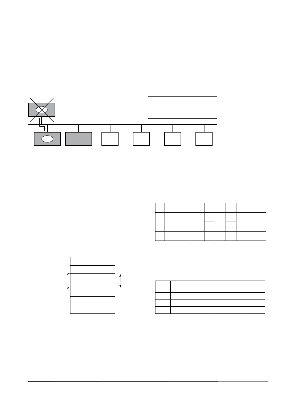
A7.3 Transfer of LAS
there are two procedures for an LM to become the LaS:
• If the LM whose value of [V(St)V(tn)] is the smallest on a segment, with the exception of the current
LaS, judges that there is no LaS on the segment, in such a case as when the segment has started up
or when the current LaS has failed, the LM declares itself as the LaS, then becomes the LaS. (With
this procedure, an LM backs up the LaS as shown in the following figure.)
• the LM whose value of [V(St)V(tn)] is the smallest on a segment, with the exception of the current
LaS, requests the LaS on the same segment to transfer the right of being the LaS, then becomes the
LaS.
LM
node address:
0x15
Slottime = 5
LM
node address:
0x16
Slottime = 5
node address: 0x10
Slottime = 5
Basic device
node address:
0xF1
Basic device
node address:
0xF2
Basic device
node address:
0xF3
Basic device
node address:
0xF4
LaS
LaS
In the event that the current LaS in
this segment (node address 0x10)
fails, the LM with the address of 0x15
takes its place to become the LaS.
LM
Fa0602.EPS
Figure A7-2. Backup of LAS
to set up a RotaMaSS as a device that is capable of backing up the LaS, follow the procedure below.
notE: When changing the settings in a
RotaMaSS, add the RotaMaSS to the segment
in which an LaS is running. after making chang-
es to the settings, do not turn off the power to the
RotaMaSS for at least 60 seconds.
(1) Set the node address of the RotaMaSS. In
general, use an address from 0x10 to
[V(Fun) – 1].
not used
LM device
not used
Basic device
Default address
Portable-device address
V (Fun)
V (Fun) + V (nun)
V (nun)
0xFF
0xFD
0xFC
0xF8
0xF7
0x10
0x00
Fa0603.EPS
Figure A7-3. Node Address ranges
(2) In the LaS settings of the RotaMaSS, set
the values of V(St), V(MRD), and V(MID) to
the same as the respective lowest capability
values in all the devices within the segment.
an example is shown below.
Sub-
index
Element
Device
1
Device
2
Device
3
Description
1
3
6
Slottime
MaxResponse
Delay
MinInterPdu
Delay
4
3
4
8
6
8
10
3
12
20
5
10
Capability value
for V(St)
Capability value
for V(MRD)
Capability value
for V(MID)
ta0601.EPS
DlmeBasicInfo (Rotamass Index xxx (SM)
Rota-
mass
In this case, set Slottime, MaxResponsetime,
and MinInterPduDelay as follows:
Subinde x
Element
Configu redLink Settings Record
(Rotamass Index xxx (SM)
Description
Setting
(Default)
V (St)
V (MRD)
V (MID)
20
6
12
(4095)
(5)
(12)
Slottime
MaxResponseDelay
MinInterPduDelay
1
3
6
ta0602.EPS
(3) In the LaS settings of the RotaMaSS, set
the values of V(Fun) and V(nun) so that they
include the node addresses of all nodes within
the same segment. (See also Figure a7-3.)