Watlow CLS User Manual
Page 82
74 CLS User’s Guide
Setup
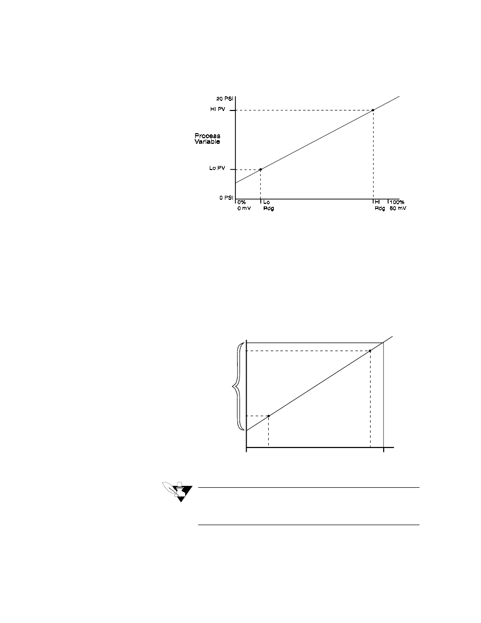
The scaling function is defined by two points on a conversion line. It
relates the high PV to the high reading and the low PV to the low
reading to define the line. The engineering units of the process variable
can be any arbitrary units. The graph below shows PSI as an example.
Before you enter the values that determine the two points for the
conversion line, you must choose an appropriate display format. The
CLS has six characters available for process variable display; select the
setting with the desired number of decimal places before and after the
decimal point. Use a display format that matches the range and
resolution of the process variable. The display format you choose is
used for the setpoint, alarms, deadband, spread, and proportional band.
The PV (Process Variable) range for the scaled input is between the PV
values that correspond to the 0% and 100% input readings. For the pulse
input, it is between the 0 Hz and 2000 Hz readings. This PV range
defines the limits for the setpoint and alarms, as shown here.
NOTE
For example linear scaling calculations, see Linear Scaling
section.
Process
Variable
InputR eading
0 PS I
0%
0 m V
0 H z
100%
60 m V
2000 H z
H iP V
Lo PV
Lo
R D G
H i
R D G
}
Linearin
}P ulse in
R ange