Tb-50 mounting instructions, 18 cls user’s guide installation, Five plastic standoffs – Watlow CLS User Manual
Page 26: Five 6-32 screws, Five cable tie wraps, One 50-pin ribbon cable
18 CLS User’s Guide
Installation
TB-50 Mounting Instructions
These steps tell you how to mount the TB-50. (Please follow these steps
exactly, so you don’t damage the terminal block, the ribbon cable, or the
controller.)
1.
Choose a mounting location. Be sure there is enough clearance to
install and remove the TB-50; it measures 3.4" long X 3.2" wide X
1.27" tall.
2.
Watlow Anafaze shipped the TB-50 to you in an antistatic bag.
Make sure these parts are also in the bag:
•
Five plastic standoffs.
•
Five 6-32 screws.
•
Five cable tie wraps.
•
One 50-pin ribbon cable.
•
Five ribbon cable clamps.
3.
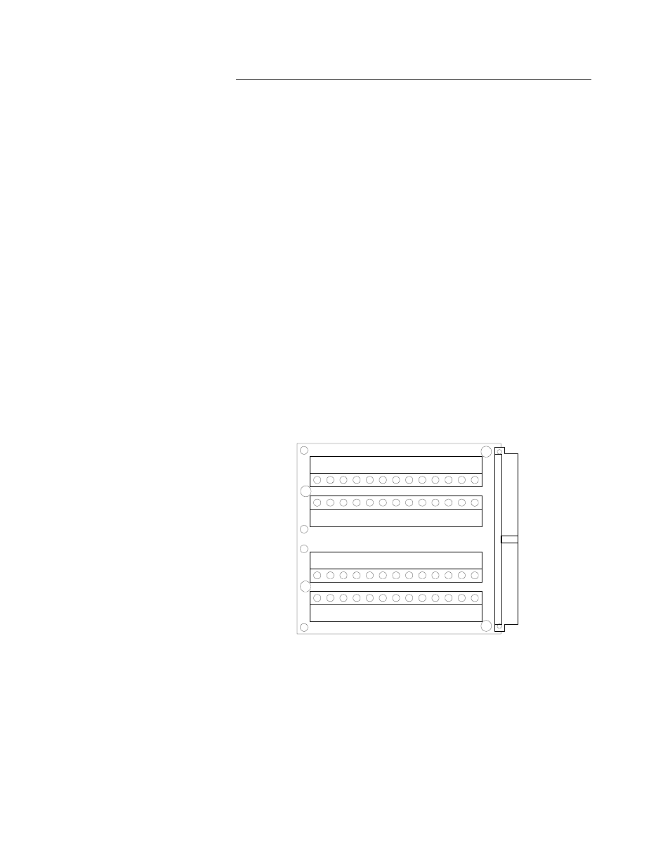
Snap four of the plastic standoffs into the four mounting holes on
the TB-50.
There are also four smaller holes on the terminal board, as shown
here. These holes are for the cable tie wraps--the plastic standoffs
won’t fit them. You’ll use these holes to secure wiring to the termi-
nal block. (See Wiring Outputs in this chapter for help installing
cable tie wraps.)
1
1
2
3
4
5
6
7
8
9
10
11
12
13A
25
24
23
22
21
20
19
18
17
16
15
14
13B
26
27
28
29
30
31
32
33
34
35
36
37
38A
50
49
48
47
46
45
44
43
42
41
40
39
38B
B
B
B
B
A
A
A
A
H oles labeled "A "are m ounting holes.
H oles labeled "B "are tie w rap holes.