Watlow CLS User Manual
Page 45
Installation
CLS User’s Guide 37
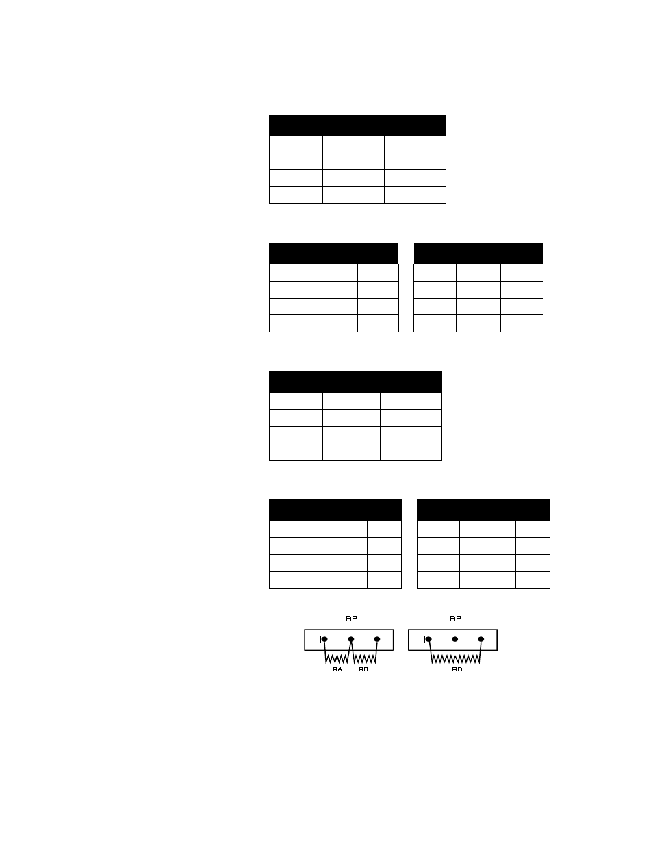
4CLS: Voltage/Current Inputs
8CLS: Voltage/Current Inputs
4CLS: RTD/Thermister Inputs
8CLS: RTD/Thermister Inputs
Place resistors RA, RB and RD in the resistor pair locations this way:
A wire trace on the printed circuit board jumpers the RC position. When
you place a resistor in the RC position, cut the wire trace that connects
the two resistor terminals.
Loop #
RC
RD
1
58
RP1
2
56
RP2
3
54
RP3
4
52
RP4
Loop
RC
RD
Loop
RC
RD
1
58
RP1
5
50
RP5
2
56
RP2
6
48
RP6
3
54
RP3
7
46
RP7
4
52
RP4
8
44
RP8
Loop #
RA/RB
RC
1
RP1
57
2
RP2
55
3
RP3
53
4
RP4
51
Loop
RA/RB
RC
Loop
RA/RB
RC
1
RP1
57
5
RP5
49
2
RP2
55
6
RP6
47
3
RP3
53
7
RP7
45
4
RP4
51
8
RP8
43
See also other documents in the category Watlow Sensors:
- 12LS Controller (111 pages)
- 8LS Controller (140 pages)
- 8PID Controller (55 pages)
- Addendum to EZwarePlus (50 pages)
- ANASCAN (62 pages)
- ANASOFT (95 pages)
- ANAWIN 2 (154 pages)
- ANAWIN 3 (23 pages)
- Calibrating Watlow Series 988 Family Process Controls (19 pages)
- CAS (98 pages)
- CAS200 (124 pages)
- CLS200 (251 pages)
- CLS200, MLS300 and CAS200 (92 pages)
- Control Console (12 pages)
- CPC400 (230 pages)
- DIN-A-MITE Style A (9 pages)
- DIN-A-MITE Style B (14 pages)
- DIN-A-MITE Style C (22 pages)
- DIN-A-MITE Style D (9 pages)
- DIN-Mount Adapter Instruction Sheet, Rev A (1 page)
- Dual DAC (4 pages)
- EM Gateway (28 pages)
- E-Safe Hybrid Relay Rev B (4 pages)
- E-SAFE II Hybrid Power Switch (4 pages)
- EZwarePlus Programming (264 pages)
- EZ-ZONE PM (111 pages)
- EZ-ZONE PM PID (125 pages)
- EZ-ZONE PM Express Limit (34 pages)
- EZ-ZONE PM Express (35 pages)
- EZ-ZONE PM Integrated Controller (181 pages)
- EZ-ZONE RM Limit Module Rev C (127 pages)
- EZ-ZONE RMA Modul (79 pages)
- EZ-ZONE RMC (236 pages)
- EZ-ZONE RME (124 pages)
- EZ-ZONE RMH (161 pages)
- EZ-ZONE RUI/Gateway (62 pages)
- EZ-ZONE RM-Scanner-Modul (140 pages)
- EZ-ZONE ST (97 pages)
- F4 External Event Board - Rev.B (2 pages)
- HG Series Mercury Displacement Relay (6 pages)
- LogicPro (296 pages)
- Mercury Relay or MDR Retrofit (13 pages)
- MICRODIN (24 pages)
- MICRODIN (106 pages)