Cls mounting procedure, Mounting environment, Steps – Watlow CLS User Manual
Page 24
16 CLS User’s Guide
Installation
CLS Mounting Procedure
NOTE
Mount the controller before you mount the terminal block
or do any wiring. The controller's placement affects place-
ment and wiring considerations for the other components
of your system.
Mounting Environment
Install the CLS in a location free from excessive (>50
º
C) heat, dust, and
unauthorized handling. The controller can mount in any panel material
up to 0.2" thick. (Make sure there is enough clearance for mounting
brackets and terminal blocks; the controller extends 6.2" behind the
panel face and the screw brackets extend 0.5" above and below it.)
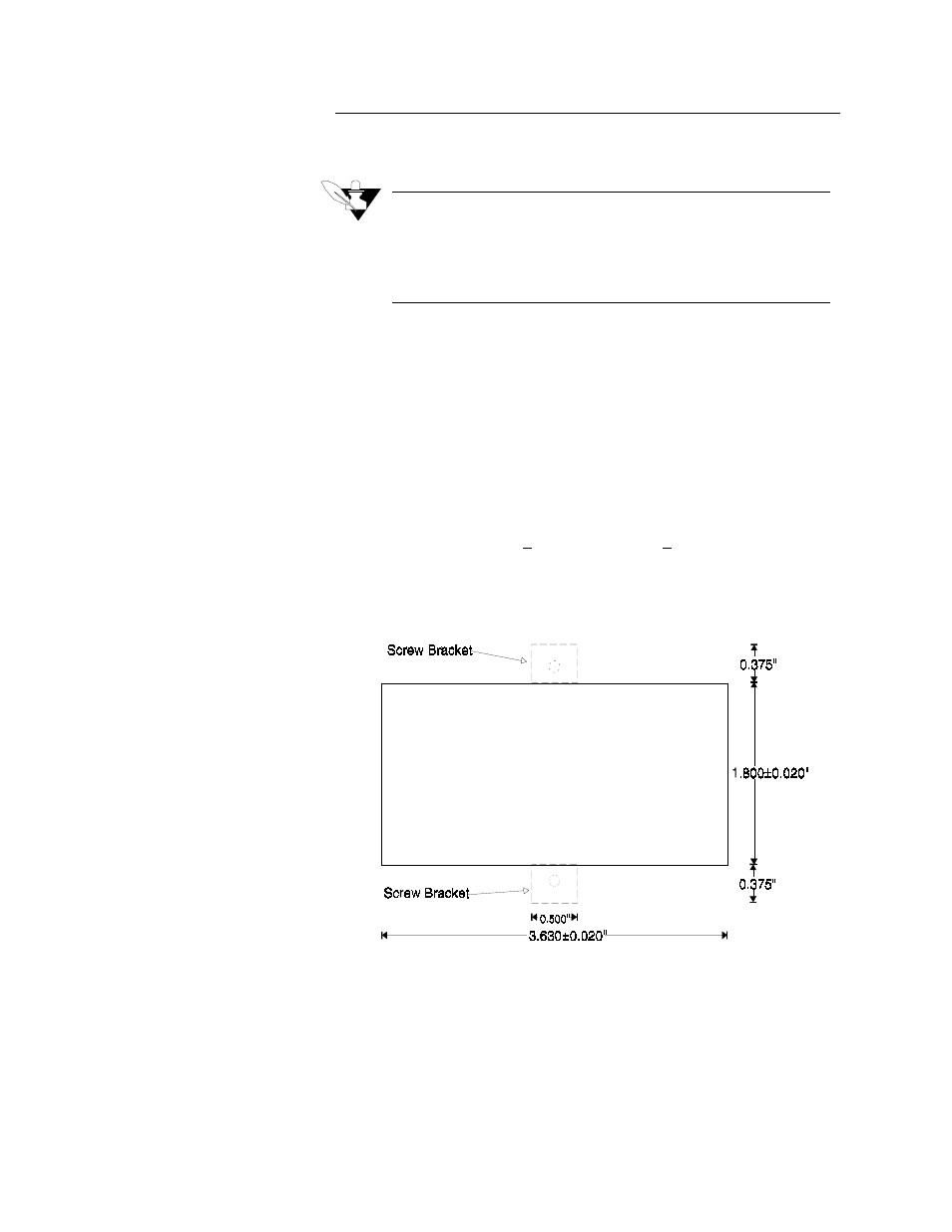
Steps:
1.
Cut a hole 3.630+0.020" long by 1.800+0.020" tall in the panel.
This figure shows the mounting hole. (The figure is not a template.)
Cut carefully; the 0.020" (0.5 mm) tolerances don't allow much
room for error. Use a punch, nibbler, or jigsaw, and file the edges of
the hole.
2.
Insert the controller into the hole through the front of the panel.
3.
Screw the top and bottom clips in place: insert the screw's lip into
the cutout in the metal housing just behind the front panel. Tighten
the screw.
4.
If you expect much panel vibration, use a rear support for the CLS
and its interconnecting cables.