Watlow CLS User Manual
Page 160
152
Appendix B: Enhanced Process Control
Now press the "Back" key several times until the normal loop display
appears. The Process Variable Retransmit will now produce an output
on Channel 2 Output which is linear and proportional to Channel 1
Process Variable.
This is not a T/C curve type of signal and requires a linear input range in
the recorder.
To complete this configuration, the Channel 2 Output must be enabled
and tailored to meet the requirements of the data-application. In this
example using a data logging recorder, the data-logger will most likely
require an analog output 4-20 mA, or 0-1 Vdc, or 1-5 Vdc, or 0-5 Vdc.
The CLS/MLS line of controllers must be used with an Watlow Anafaze
Dual Dac [Digital to Analog Converter] or SDAC (Serial Digital to
Analog Converter) for proper signal conversion.
The Dual Dac accuracy on retransmit is .75% of reading which matches
the standard T/C rated accuracy statement of .75% of reading.
For higher accuracies of .05% of full scale, the SDAC is recommended.
Please consult the SETUP Section of this manual for information on
setting up the other options of the controller.
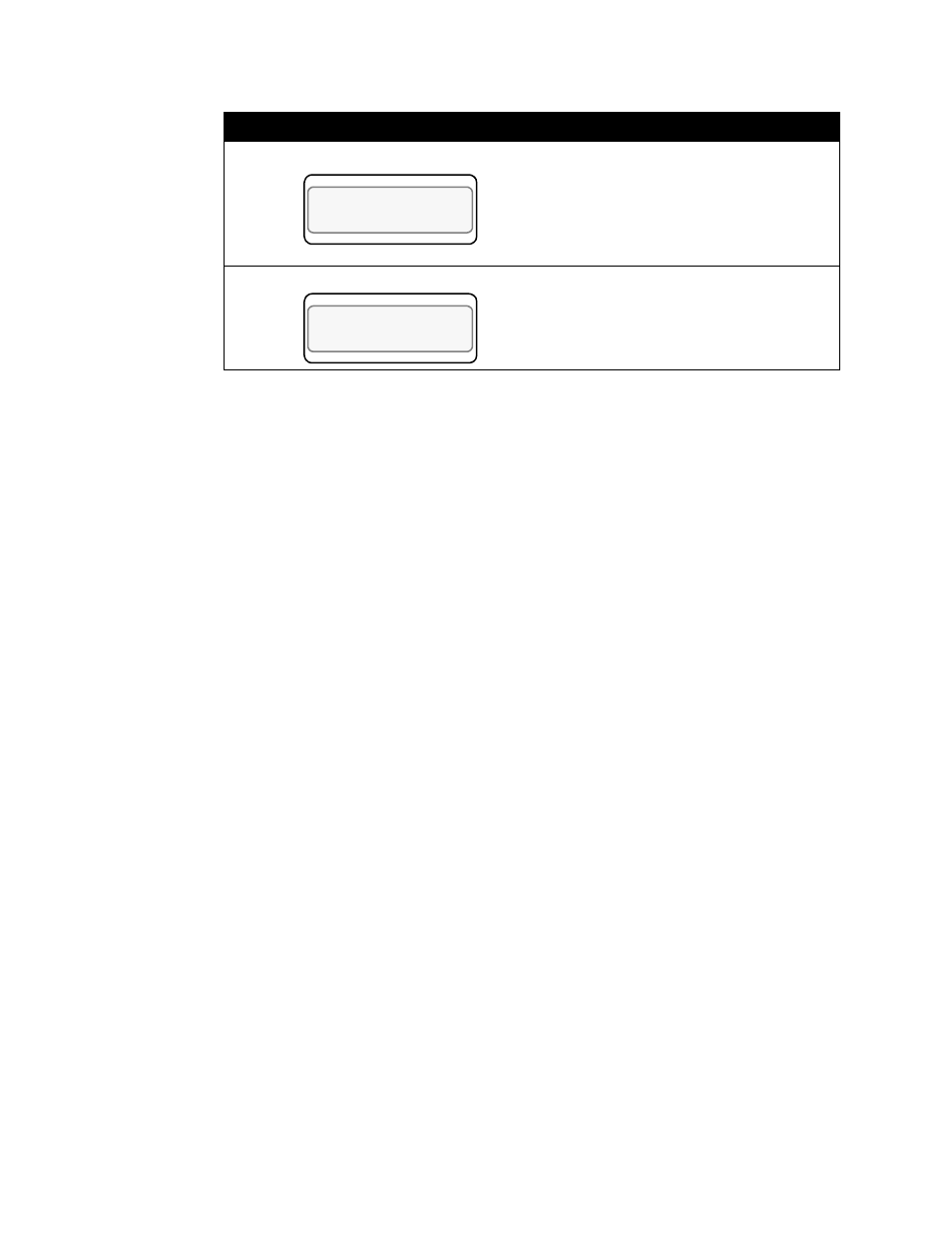
Enter the maximum output percentage,
from 0 to 100%. For this example we will
assume a full span with a maximum of
100%.
Press Enter.
The PV retransmit section of the CLS
programming is now completed. You are
not using the cool output of loop 2 for
retransmitting a PV, so choose None.
Press Enter.
Display
User Input
LOOP PROCESS UNITS
ALARM SETPOINT STATUS OUT%
02 HEAT RETRANS
MAX OUT%? 100
LOOP PROCESS UNITS
ALARM SETPOINT STATUS OUT%
02 COOL OUTPUT
RETRANS PV? NONE