Single loop display, Navigating in bar graph display – Watlow CLS User Manual
Page 62
54 CLS User’s Guide
Using the CLS
The next table explains the symbols you see on the bottom line of Bar
Graph display. These symbols appear when the controller is in both dual
output mode and single output mode. If an alarm occurs, the controller
automatically switches to Single Loop display and shows an alarm code.
Navigating in Bar Graph Display
•
Press Yes (up) or No (down) to see Bar Graph Display for the Pulse
Input loop.
•
Press Enter twice to start Bar Graph scanning mode. In scanning
mode, the controller alternately displays the first four loops and then
the pulse input loop for three seconds each.
•
Press any key to stop scanning mode.
•
From Bar Graph Display, press Back once to go to Single Loop dis-
play.
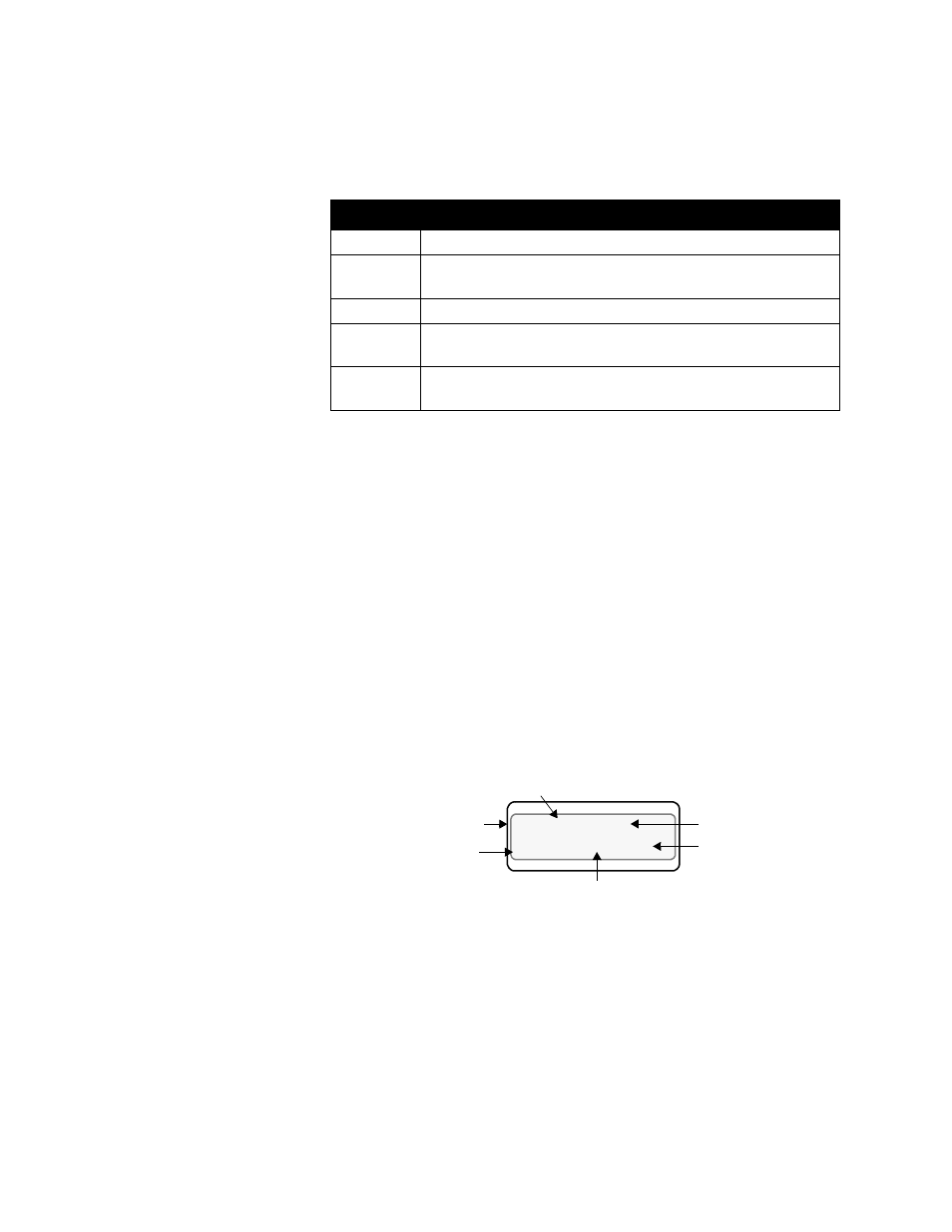
Single Loop Display
Single Loop display (below) shows detailed information for only one
loop. If the heat and cool outputs are enabled, Single Loop display looks
like this:
The control status indicator shows HEAT or COOL if the loop is in
automatic control, and MAN or TUNE if the loop is in manual control.
Symbol
Symbol’s Meaning
M
One or both outputs enabled. Loop is in manual control.
A
Only one output (heat or cool, but not both) is enabled. Loop is
in automatic control.
T
Loop is in Autotune mode.
H
T
Both heat and cool outputs are enabled. Loop is in Automatic
control and heating.
C
L
Both heat and cool outputs are enabled. Loop is in Automatic
control and cooling.
LOOP PROCESS UNITS
ALARM SETPOINT STATUS OUT%
02 160
º
F
180 AUTO 100
Engineering
Units
Output
percentage
Control Status
Setpoint
Loop Number
or Name
Process Variable