General wiring, Power wiring and controller test, Connecting power and tb-50 to cls – Watlow CLS User Manual
Page 33
Installation
CLS User’s Guide 25
General Wiring
The following sections explain how to test your installation before you
connect power to it and how to connect inputs and outputs to it.
Power Wiring and Controller Test
When you have installed each component of the controller and the TB-
50 (if used), use this checklist to connect them. These instructions are
written so that non-electricians can understand them. If you are an
experienced electrician, they may seem elementary to you. If so, feel
free to skim them.
Connecting Power and TB-50 to CLS
1.
Remove the temporary covers on the CLS housing.
2.
The plug-in power supply, included with your controller, has two
bare wires. The + side connects to TB2-1, and the - side to TB2-2.
As a precaution, you should check the polarity of the wires with a
multimeter (color coding of the wires is not always reliable with
older power supplies). Do not turn on the AC power yet.
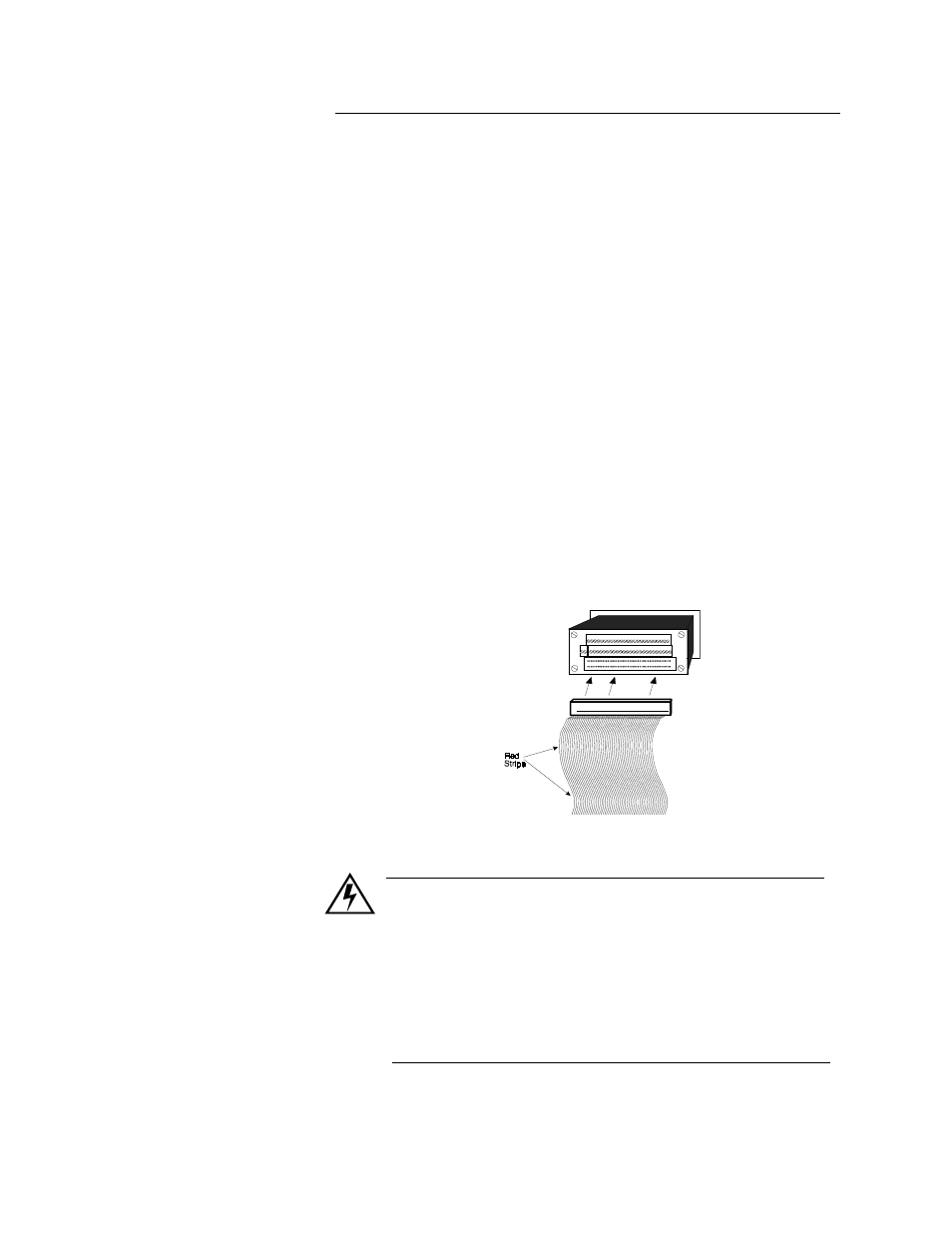
3.
Connect the ribbon cable to the controller, as shown here. Plug it in
so the red stripe is on the left side as you face the back of the con-
troller.
4.
Connect the ribbon cable to the TB-50. The cable is keyed, so you
cannot insert it backwards.
WARNING
Do not turn on the AC power yet. Test the connections first,
as explained in the Connections Test section below.
Excessive voltage to the CLS will damage it, and you will
need to return it to Watlow Anafaze for repair. If you use
your own power supply, read the next section completely
and follow its instructions before you apply power to the
CLS.