General wiring recommendations – Watlow CLS User Manual
Page 28
20 CLS User’s Guide
Installation
General Wiring Recommendations
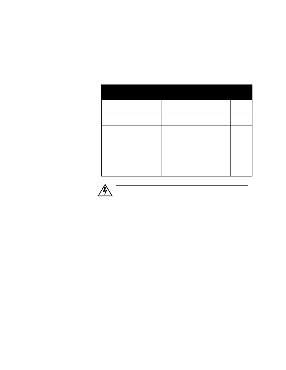
Use the cables below or their equivalent. For best results, use
appropriate materials, proper installation techniques and the correct
equipment. For example, choose wire type by function, installation
requirements, and the likelihood of mechanical or electrical problems
at your installation.
WARNING
Never wire bundles of low power controller circuits next to
bundles of high power AC wiring. Instead, physically sepa-
rate high power circuits from the controller. If possible,
install high voltage AC power circuits in a separate panel.
•
Use stranded wire. Solid wire is used for fixed service; it makes
intermittent connections when you move it for maintenance.
•
Use #20 or #22 AWG wire. Larger or smaller sizes may be difficult
to install, may break easily, or may cause intermittent connections.
•
Use shielded wire. (The electrical shield helps protect the CLS from
electrical noise.) Connect one end of the input wiring shield to the
CLS panel's 120 Vac panel ground, and connect one end of the out-
put wiring shield to the CLS panel's 120 Vac panel ground. (Some
installations may require a different shield configuration. Contact
Watlow Anafaze for more information if these instructions do not
apply to your system.)
For more noise suppression measures, see Noise Suppression.
Function
MFR P/N
No. of
Wires
AWG
Analog inputs
Belden #9154
Belden #8451
2
2
20
22
RTD Inputs (4 & 8 CLS)
Belden #8772
Belden #9770
3
3
20
22
T/C Inputs
T/C Ext. Wire
2
20
Digital PID outputs and Dig-
ital I/O
Belden #9539
Belden #9542
Ribbon Cable
9
20
50
24
24
Computer Communication:
RS232 or RS485
Belden #9729
Belden #9730
Belden #9842
Belden #9843
4
6
4
6
24
24
24
24