Watlow CLS User Manual
Page 162
154
Appendix B: Enhanced Process Control
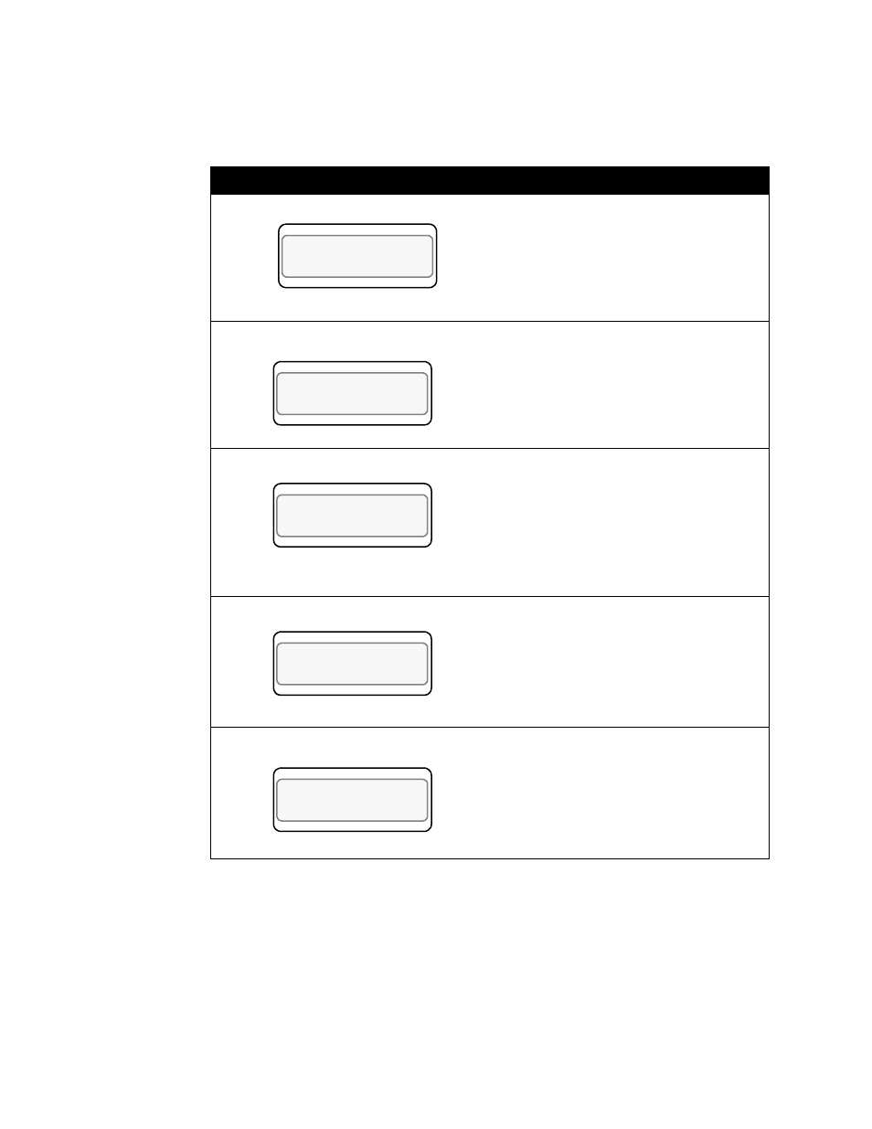
First, switch the controller to display loop 2, which will be the
secondary loop, and then enter the 3-key sequence to display the
following:
Display
User Input
Press Yes to setup the Cascade parame-
ters with loop 2 as the secondary loop.
Enter 01 to make loop 1 the primary loop.
Press Enter.
The base setpopint corresponds to the 0%
level output of the primary channel. Enter
the base SP of the secondary loop. For
this example we will assume a base SP of
150°F, which is the desired water temper-
ature.
Press Enter.
Enter the minimum SP of the secondary
loop. For this example we will use a mini-
mum SP of -350°F. Normal cascade
applications will not require this to be
changed.
Press Enter.
Enter the maximum SP of the secondary
loop. For this example we will use a max-
imum SP of 1400°F. Normal cascade
applications will not require this to be
changed.
Press Enter.
LOOP PROCESS UNITS
ALARM SETPOINT STATUS OUT%
SETUP LOOP 02
CASCADE?
LOOP PROCESS UNITS
ALARM SETPOINT STATUS OUT%
02 CASCADE
PRIM. LOOP? 01
LOOP PROCESS UNITS
ALARM SETPOINT STATUS OUT%
02 CASCADE
BASE SP? 150
LOOP PROCESS UNITS
ALARM SETPOINT STATUS OUT%
02 CASCADE
MIN SP? -350
LOOP PROCESS UNITS
ALARM SETPOINT STATUS OUT%
02 CASCADE
MAX SP? 1400