Watlow CLS User Manual
Page 159
Appendix B: Enhanced Process Control
151
1) First, set up the standard control loop parameters according to the fur-
nace application, in this case on loop 1.
2) Select another unused PID output for retransmitting the thermocouple
value (for example, loop 2 heat output).
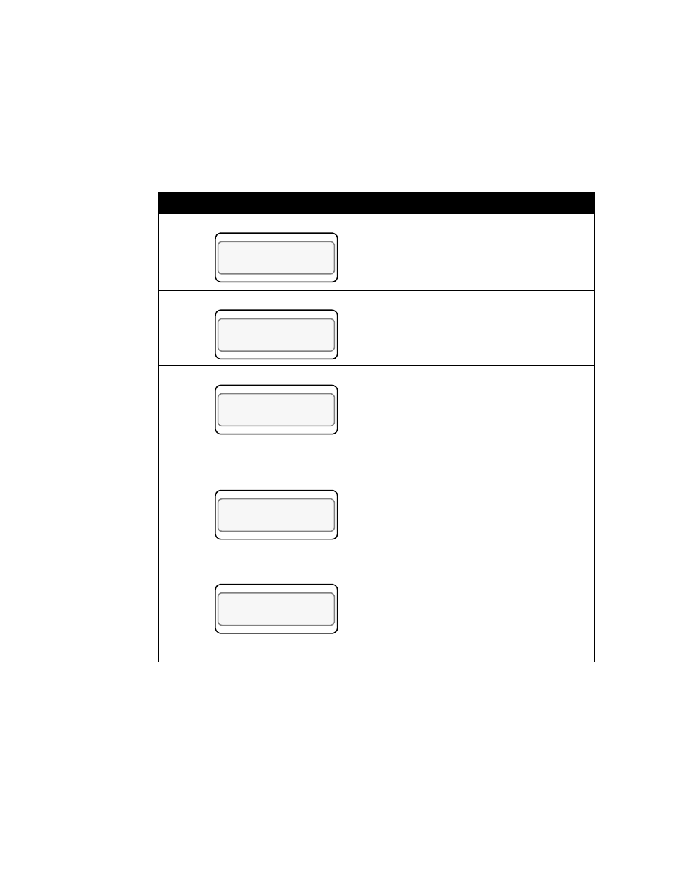
3) Change the display to loop 2, and then enter the 3-key sequence to
display the following:
Display
User Input
Press Yes.
Enter 01 for loop 01 PV.
Press Enter.
Enter the minimum input value, which
will correspond to the minimum output
percentage.
For a range of 0-1000 °F, the minimum
input value is 0 °F. Change the MIN INP
to 0.
Press Enter.
Enter the minimum output percentage,
from 0 to 100%. For this example we will
assume a full span with a minimum of
0%.
Press Enter.
Enter the maximum input value, which
corresponds to the maximum output per-
centage.
For a range of 0-1000 °F, the maximum
input value is 1000 °F. Change the MAX
INP to1000.
Press Enter.
LOOP PROCESS UNITS
ALARM SETPOINT STATUS OUT%
SETUP LOOP 02
PV RETRANSMIT?
LOOP PROCESS UNITS
ALARM SETPOINT STATUS OUT%
02 HEAT OUTPUT
RETRANS PV? 01
LOOP PROCESS UNITS
ALARM SETPOINT STATUS OUT%
02 HEAT RETRANS
MIN INP? 0
LOOP PROCESS UNITS
ALARM SETPOINT STATUS OUT%
02 HEAT RETRANS
MIN OUT%? 0
LOOP PROCESS UNITS
ALARM SETPOINT STATUS OUT%
02 HEAT RETRANS
MAX INP? 1000