7 push-motion operation – IAI America PCON-CY User Manual
Page 80
70
5. Operation Using I/O Signals
5.3.7 Push-motion
Operation
Just like you can with an air cylinder, you can maintain the actuator in a condition where the tip of the rod is pushing a work.
Accordingly, the actuator can be used with systems that clamp, press-fit or otherwise push works.
This function is enabled by entering a current-limiting value in the “Push” field of the position table.
* If the “Push” field contains “0,” positioning operation is applied. If the value in this field is other than “0,” push-motion
operation is applied.
The push torque [N] is determined by the current-limiting value [%] in the “Push” field.
[Basics of push-motion operation]
[1] Enter a current-limiting value in the “Push” field for the front end (Position No. 1) to define that a front end command will
be implemented as push-motion operation.
* Determine an appropriate push force based on the characteristics of the work (shape, material, etc.), and obtain a
current-limiting value by using the “push force vs. current-limiting value” correlation diagram (explained later) of the
actuator as a reference.
[2] In the “Positioning band” field, enter the maximum travel (relative distance) from the front end permitted during
push-motion operation.
(Consider a position error that may generate when the work is installed, as well as a possible depression if the work is
made of elastic material.)
[3] If it is possible for the system to miss the work, use the zone output signal to detect missed work. To do this, enter
appropriate values in the “Zone +” and “Zone –” fields to specify a range within which the work is deemed to have been
contacted successfully.
[4] Change the value of Parameter No. 6 (Push-motion completion judgment time), if necessary.
(The factory setting is 255 msec, which is the maximum value that can be set for this parameter.)
[5] Change the value of Parameter No. 34 (Push speed), if necessary.
(The factory setting is different in accordance with the actuator model.)
* For details on these parameters, refer to Chapter 6, “Parameter Settings.”
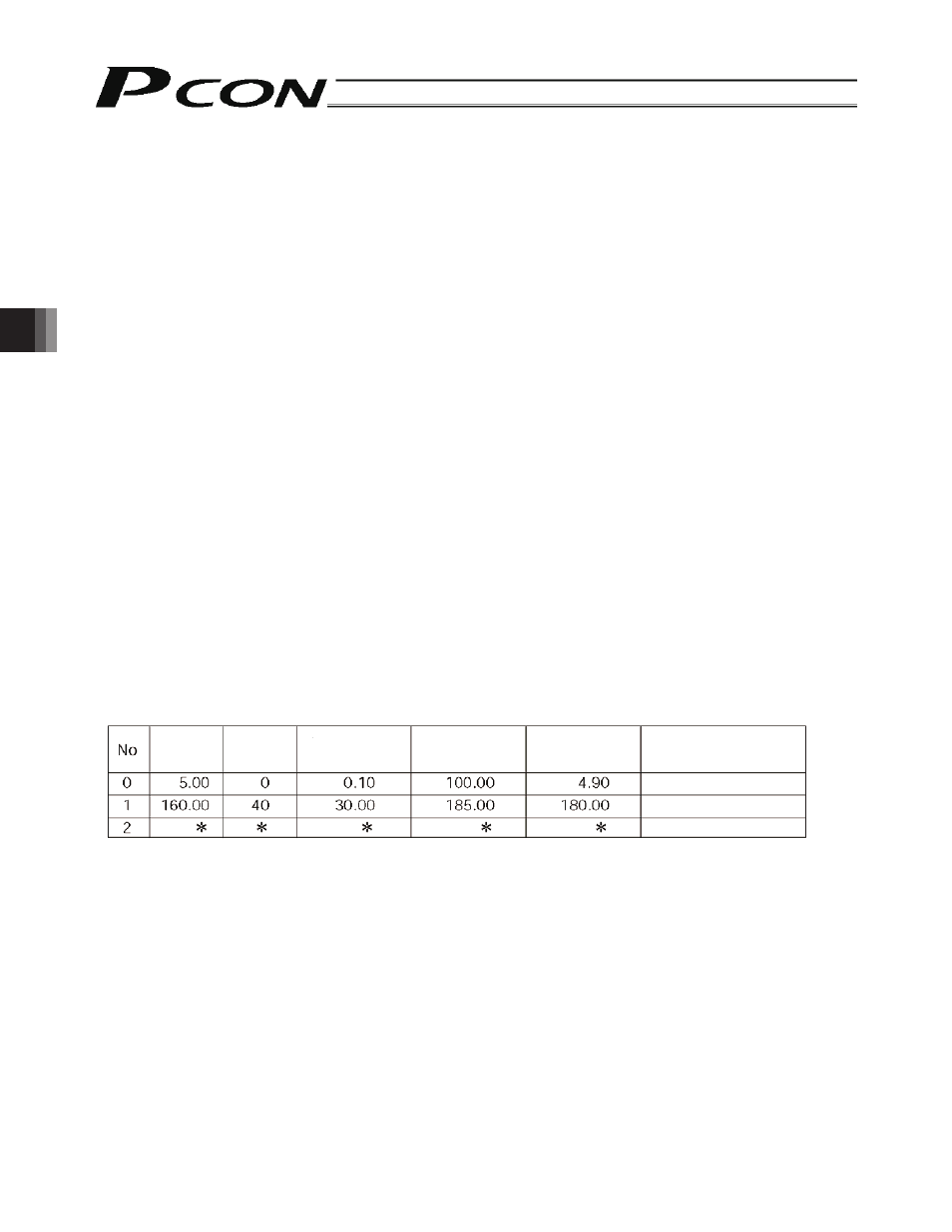
(Example) An example with a rod actuator with a 200-mm stroke, where the current-limiting value is set to 40%,
maximum travel in push-motion operation to 20 mm, and successful contact range to between 180 and
185 mm, is explained.
Under No. 1 in the position table, enter “160” (mm) in the “Position” field, “40” (%) in the “Push” field, “30”
mm in the “Positioning band” field, “185” (mm) in the “Zone +” field, and “180” (mm) in the “Zone –” field.
Example of position table
Positioning
band [mm]
Position
[mm]
Push
[%]
Comment
Zone +
[mm]
Zone –
[mm]
Rear end (Standby position)
Front end
Intermediate point