9 connecting the actuator, 1 motor relay cable – IAI America PCON-CY User Manual
Page 39
29
3. Installation and W
iring
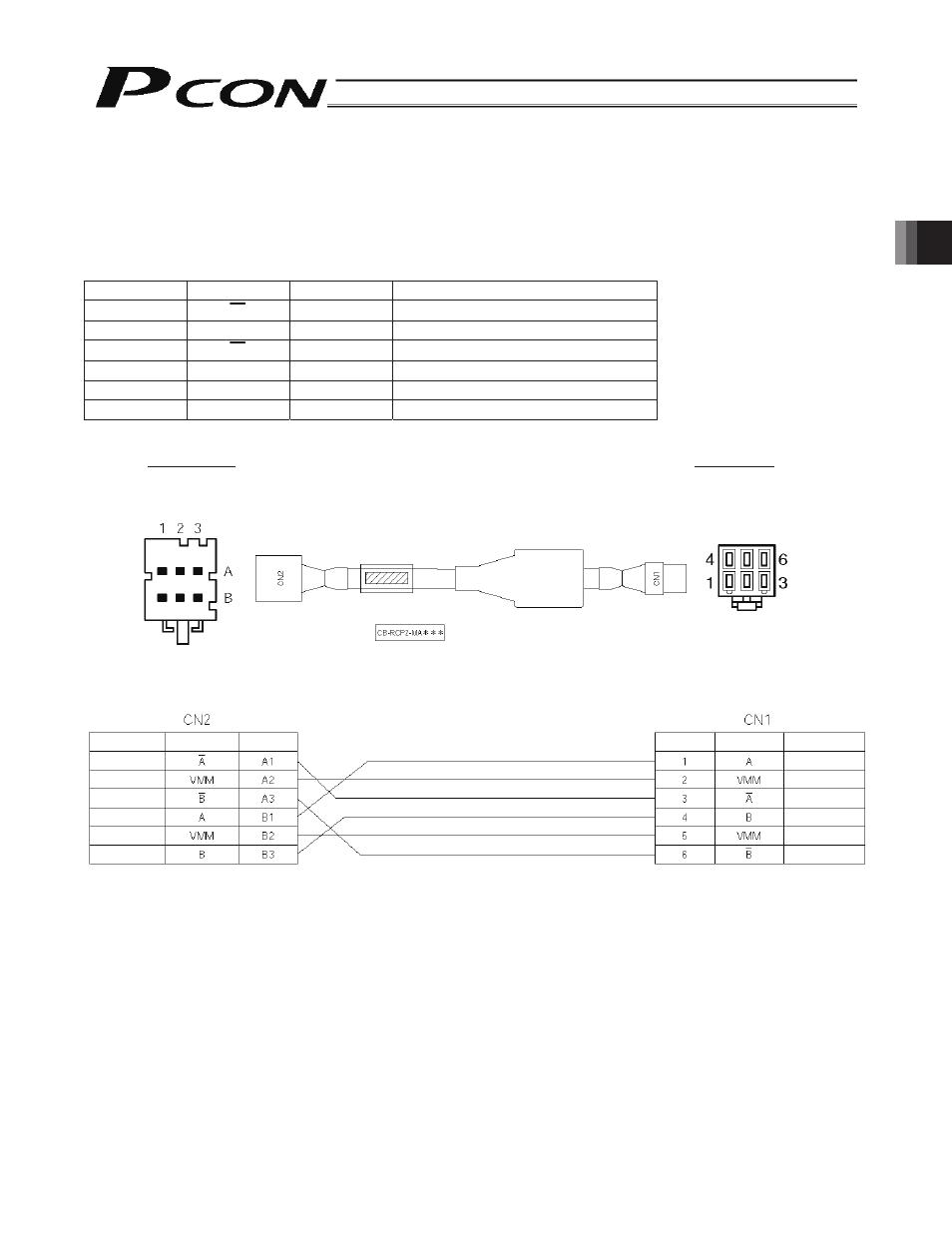
3.9 Connecting
the
Actuator
3.9.1
Motor Relay Cable
• Connect the motor relay cable to the MOT connector.
Signal table of controller-end connector (CN2)
Pin No.
Signal
Wire color
Description
A1
A
Orange
Motor drive line (phase -A)
A2
VMM
Gray
Motor power line
A3
B
White
Motor drive line (phase -B)
B1
A
Yellow
Motor drive line (phase +A)
B2
VMM
Pink
Motor power line
B3
B
Yellow (Green) Motor drive line (phase +B)
Controller end
Actuator end
CN2 pin layout
CN1 pin layout
Housing: 1-1318119-3
(AMP)
Housing: SLP-06V
(J.S.T.
Mfg.)
Receptacle contact: 1318107-1
Socket contact: BSF-21T-P1.4
Orange
Gray
White
Yellow
Pink
Yellow (Green)
Yellow
Gray
Orange
Yellow (Green)
Pink
White
Cable color
Signal
abbreviation
Pin No.
Cable color
Signal
abbreviation
Pin No.
- ERC2 (138 pages)
- ERC2 (188 pages)
- ERC3 (438 pages)
- ERC (153 pages)
- RCA-E (53 pages)
- RCA-P (42 pages)
- RCB-101-MW (38 pages)
- RCP2-C (178 pages)
- RCS-E (102 pages)
- RCA-A4R (72 pages)
- RCA-RA3C (114 pages)
- RCA-SRA4R (56 pages)
- RCA2-RA2AC (100 pages)
- RCA2-SA2AC (92 pages)
- RCA2-TA4C (134 pages)
- RCD-RA1D (40 pages)
- RCP2-BA6 (72 pages)
- RCP2-GRSS (130 pages)
- RCP2-HS8C (126 pages)
- RCP2-RA2C (120 pages)
- RCP2-RTBS (80 pages)
- RCP2W-SA16C (46 pages)
- RCP3-RA2AC (60 pages)
- RCP4-RA5C (82 pages)
- RCP4-SA5C (94 pages)
- RCP4W (96 pages)
- RCS2-F5D (142 pages)
- RCS2-GR8 (46 pages)
- RCS2-RN5N (80 pages)
- RCS2-RT6 (60 pages)
- RCS2-SA4C (258 pages)
- RCS2-TCA5N (62 pages)
- RCL-SA1L (66 pages)
- RCL-RA1L (56 pages)
- RCLE-GR5L (46 pages)
- IK Series (16 pages)
- FS (84 pages)
- IF (76 pages)
- ISB (114 pages)
- ISDA (126 pages)
- ISDB (116 pages)
- ISPWA (90 pages)
- NS (78 pages)
- ICS(P)A (16 pages)
- RS (46 pages)