5 external connection diagram, 24 3. installation and w iring – IAI America PCON-CY User Manual
Page 34
24
3. Installation and W
iring
Brown 1
Red 1
Orange 1
Yellow 1
Green 1
Blue 1
Purple 1
Gray 1
White 1
Black 1
Brown 2
Red 2
Orange
Gray
White
Yellow
Pink
Yellow (Green)
Yellow
Orange
(black 2)
Orange
(red 2)
Yellow
(black 1)
Yellow
(red 1)
White
(black 1)
White
(red 1)
Light blue
(black 1)
Light blue
(red 1)
For teaching pendant/PC
connection
Brake release
switch
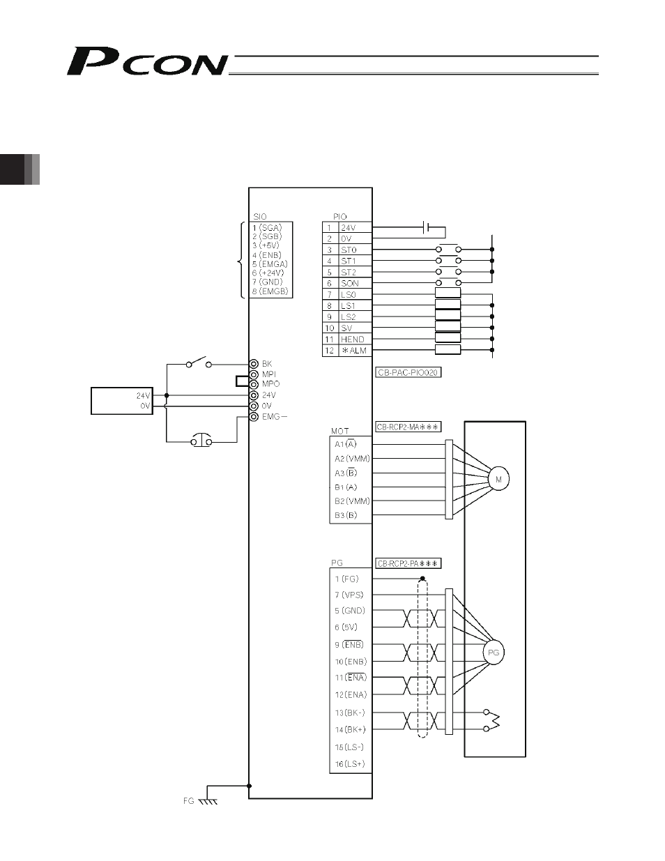
PCON-CY controller
Flat cable
External EMG
switch
Input power
supply
24 VDC
Terminal block
24-VDC power
supply for I/O signals
0 V (NPN specification)
24 V (PNP specification)
Load
0 V (NPN specification)
24 V (PNP specification)
Load
Load
Load
Load
Load
Tighten together with a mounting screw.
Motor relay cable
Actuator
Motor
Encoder relay cable
Encoder
Holding brake
3.5
External Connection Diagram
An example of standard wiring is shown below.
(Note)
The PIO signal names are those based on the proximity switch type.
The color of the encoder relay cable is different for the robot cable specification. Refer to 3.9.2, “Encoder Relay
Cable.”