3 standard type, 1 explanation of i/o signals – IAI America PCON-CY User Manual
Page 65
55
5. Operation Using I/O Signals
5.3 Standard
Type
This type assumes situations where the system must achieve high productivity or uses push-motion operation. Use this type if
your application meets the following conditions:
[1] Use the zone output signal to quicken the operation timings with respect to the respective equipment and thereby
reduce the tact time.
[2] Use the zone output signal as an interlock signal to prevent contact with peripheral equipment.
[3] When missed work must be detected in push-motion operation, use the zone output signal as a “simple yardstick” to
determine if the work has been contacted properly or missed.
Caution:
The controller is shipped with the proximity switch type pre-selected. If you want to use the standard type, set
the value of Parameter No. 25 (PIO pattern selection) to “1.”
→ Refer to Chapter 6, “Parameter Settings”
5.3.1
Explanation of I/O Signals
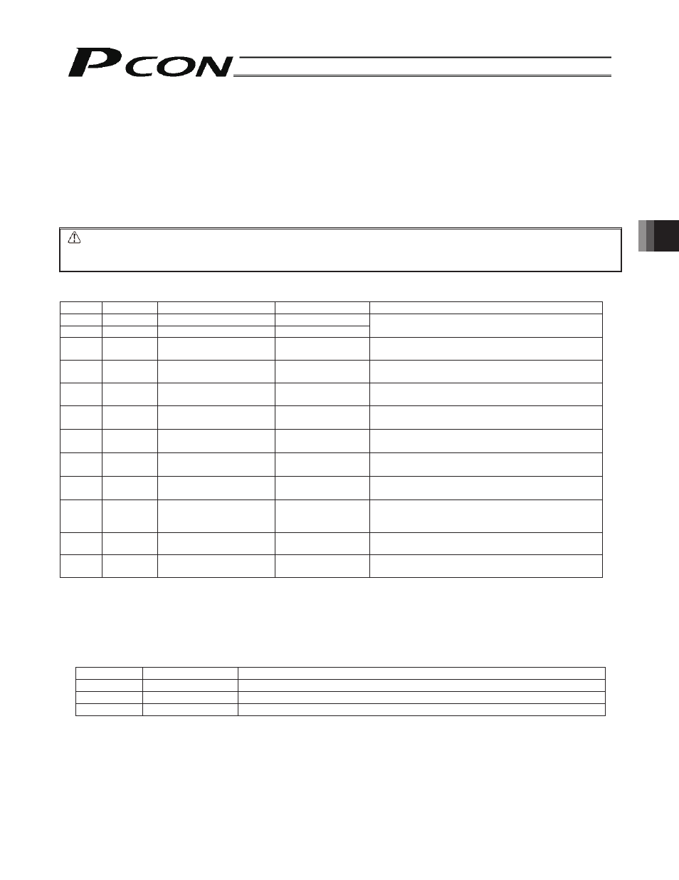
Pin No. Wire color
Signal name
Signal abbreviation
Function overview
1
Brown 1
+24 V
P24V
2
Red 1
0 V
N
I/O power supply
3 Orange
1
Rear end move
command input
ST0
Move command to the rear end
4 Yellow
1
Front end move
command input
ST1
Move command to the front end
5 Green
1
Intermediate point move
command input
ST2
Move command to the intermediate point
6
Blue 1
Servo-on command input SON
The servo remains on while this signal is ON.
The servo remains off while this signal is OFF.
7 Purple
1
Rear end positioning
complete output
PE0
This signal turns ON upon completion of movement
to the rear end.
8 Gray
1
Front end positioning
complete output
PE1
This signal turns ON upon completion of movement
to the front end.
9 White
1
Intermediate point
positioning complete output
PE2
This signal turns ON upon completion of movement
to the intermediate point.
10 Black
1
Zone output
PZONE
This signal remains ON while the actuator is inside the
range set in the “Zone +” and “Zone –” fields of the
position table.
11
Brown 2
Homing complete output HEND
This signal is OFF immediately after the power is
turned on, and turns ON once homing is completed.
12
Red 2
Alarm output
*ALM
This signal remains ON while the actuator is
normal, and turns OFF if an alarm has occurred.
Move Command Input for Each Position (ST0, ST1, ST2)
Since the number of positioning points is limited to three, you can use these inputs just like when controlling an air cylinder.
While each signal remains ON, the actuator moves to the target position.
If the signal turns OFF before the movement is completed, the actuator will decelerate to a stop.
Before executing each move command, enter a target position as an absolute coordinate in the “Position” field under one
of Nos. 0 to 2 in the position table.
Input signal
Target position
Remarks
ST0
Rear end
The target position is defined in the “Position” field under Position No. 0.
ST1
Front end
The target position is defined in the “Position” field under Position No. 1.
ST2
Intermediate point The target position is defined in the “Position” field under Position No. 2.
Servo-on Command Input (SON)
The servo remains on while this signal is ON.
To ensure safety, it is recommended that the PLC be configured to monitor the condition of the entire system and turn ON
this signal once all conditions required for movement are satisfied.