10 connecting the i/o flat cable – IAI America PCON-CY User Manual
Page 41
31
3. Installation and W
iring
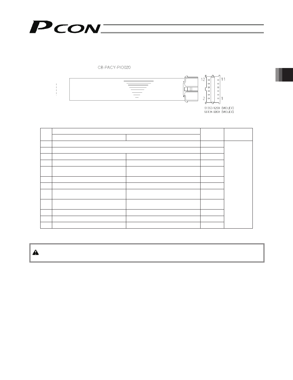
3.10 Connecting the I/O Flat Cable
Signal name
No.
Proximity switch type
Standard type
Color Wiring
1 24
V Brown-1
2 0
V Red-1
3
Rear end move command input
Rear end move command
Orange-1
4
Front end move command input
Front end move command
Yellow-1
5
Intermediate point move command
input
Intermediate point move command
Green-1
6
Servo-on command input
Servo-on command input
Blue-1
7
Rear end detection output
Rear end positioning complete output
Purple-1
8
Front end detection output
Front end positioning complete
output
Gray-1
9
Intermediate point detection output
Intermediate point positioning
complete output
White-1
10 Ready
output
Zone
output
Black-1
11 Homing complete output
Homing complete output
Brown-2
12 Alarm output
Alarm output
Red-2
Flat cable
(pressure-
welded)
Warning: When checking the continuity of the flat cable, exercise due caution not to bend the female pins on the
connector outward. It may cause contact failure, resulting in malfunction.
Red 2
Brown 1
Cable type:
Housing:
Contact: