IAI America PCON-CY User Manual
Page 63
53
5. Operation Using I/O Signals
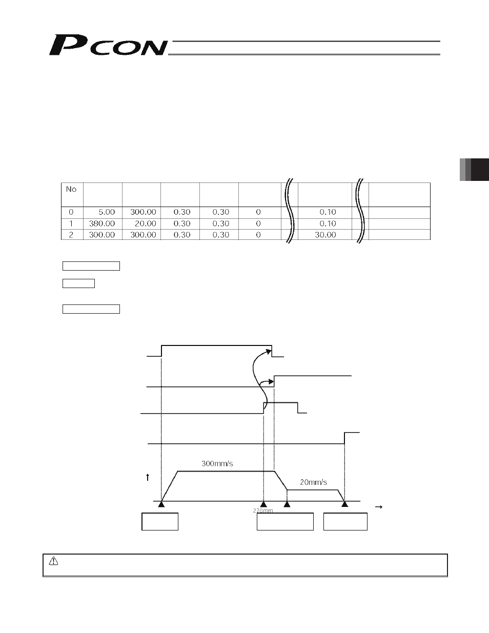
Positioning
band [mm]
Position
[mm]
Speed
[mm/s]
Acceleration
[G]
Deceleration
[G]
Push
[%]
Rear end
Front end
Intermediate point
Comment
z Speed Change during Movement
If the work is made of soft material or is a bottle or has other shape that tips over easily, one of the following two methods
can be used to prevent the work from receiving vibration or impact upon stopping:
[1] Decrease the deceleration to make the deceleration curve more gradual.
[2] Initially move the actuator at the rated speed, and decrease the feed speed shortly before the target position.
An example of [2], or decreasing the feed speed, is explained.
(Example) When moving the actuator from the rear end to the front end, use the intermediate point as a dummy point.
Set the feed speed to 300 mm/s to the intermediate point, and decrease it to 20 mm/s after the
intermediate point.
Example of position table
Operation timings
PLC processing 1:
The rear end move command signal (ST0) and front end move command signal (ST1) turn OFF,
and the intermediate point move command signal (ST2) turns ON.
Operation:
[1]
The actuator starts moving toward the intermediate point.
[2]
When the actuator reaches the position corresponding to 270 mm, the intermediate point
detection output (LS2) turns ON.
PLC processing 2:
The intermediate point move command signal (ST2) turns OFF, and the front end move
command signal (ST1) turns ON.
[3]
The actuator decelerates from 300 mm/s to 20 mm/s, and stops at the front end.
Caution:
By setting a wide positioning band for the intermediate point, smooth speed change can be achieved without
the actuator stopping at the intermediate point.
Intermediate move
command input (ST2)
Front end move
command input (ST1)
Intermediate point
detection output (LS2)
Front end detection
output (LS1)
Speed
Rear end
5 mm
Intermediate point
300 mm
Front end
380 mm
Time