5 positioning operation – IAI America PCON-CY User Manual
Page 61
51
5. Operation Using I/O Signals
Positioning
band [mm]
Position
[mm]
Speed
[mm/s]
Acceleration
[G]
Deceleration
[G]
Push
[%]
Rear end
Front end
Intermediate point
Comment
5.2.5 Positioning
Operation
This section explains how to move the actuator from the rear end to the front end, by using an actuator with a 400-mm stroke
as an example.
Although the actuator is not stopped at the intermediate point in this example, you can increase the positioning band and use
the intermediate point detection output signal (LS2) just like the zone output signal.
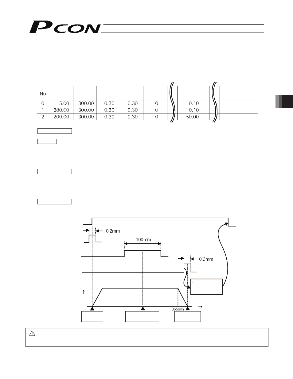
Example of position table
Operation timings
PLC processing 1:
The rear end move command signal (ST0) and intermediate point move command signal (ST2)
turn OFF, and the front end move command signal (ST1) turns ON.
Operation:
[1]
The actuator starts moving toward the front end.
[2]
When the actuator passes the position corresponding to 5.1 mm, the rear end detection
output (LS0) turns OFF.
[3]
When the actuator reaches the position corresponding to 150 mm, the intermediate point
detection output (LS2) turns ON. The LS2 turns OFF once the actuator passes the position
corresponding to 250 mm.
PLC processing 2:
If necessary, use the intermediate point detection output (LS2) as a trigger signal for peripheral
equipment.
[4]
The actuator starts decelerating after reaching the position corresponding approx. 365 mm.
[5]
When the actuator passes the position corresponding to 379.9 mm, the front end detection
output (LS1) turns ON.
[6]
The actuator stops after reaching the position corresponding to 380 mm.
PLC processing 3:
When the front end detection output (LS1) turns ON, the sequence processing is performed at the
front end. Once the sequence processing is completed, the front end move command signal
(ST1) turns OFF.
Caution:
Design a ladder sequence circuit where only one move command signal turns ON at a given time. If two or
more signals are input simultaneously, the signals will be processed according to the set priorities.
Priorities: [1] Rear end, [2] front end, [3] intermediate point
Front end move
command input (ST1)
Rear end detection
output (LS0)
Intermediate point
detection output (LS2)
Front end detection
output (LS1)
Speed
Rear end
5 mm
Intermediate point
200 mm
Front end
380 mm
Time
Sequence is
performed at
the front end