2 encoder relay cable – IAI America PCON-CY User Manual
Page 40
30
3. Installation and W
iring
3.9.2
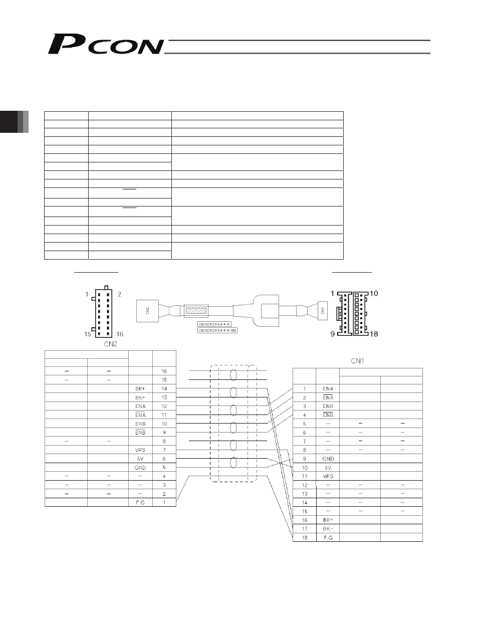
Encoder Relay Cable
• Connect the encoder relay cable to the PG connector.
Signal table of controller-end connector (CN2)
Pin No.
Signal abbreviation
Description
1 F.G
Shielded
wire
2 -
(Not
used)
3 -
(Not
used)
4 -
(Not
used)
5 GND
6 5V
Encoder power output
7
VPS
Encoder control signal output
8 -
(Reserved)
9
ENB
10 ENB
Encoder differential signal phase-B input
11
ENA
12 ENA
Encoder differential signal phase-A input
13
BK -
Brake power –
14
BK +
Brake power +
15 -
16 -
(Not used)
Controller end Actuator
end
CN2 pin layout
CN1 pin layout
Housing: XMP-18V
(J.S.T.
Mfg.)
Contact: BXA-001T-P0.6
Retainer: XMS-09V
Purple
White (with purple)
Blue
White (with blue)
Yellow
White (with yellow)
Green
Red
White (with red)
Drain
Red
Gray
Brown
Green
Purple
Pink
Yellow
Orange
Blue
Drain
Brown
Green
Purple
Pink
Blue
Orange
Yellow
Red
Gray
Drain
Blue
White (with blue)
Yellow
White (with yellow)
White (with red)
Red
Green
Purple
White (with purple)
Drain
Cable color
Signal
abbreviation
Pin No.
Cable color
Signal
abbreviation
Pin No.
Standard cable
Robot cable
Robot cable
Standard cable
Standard cable
Robot cable
Housing: PHDR-16VS (J.S.T. Mfg.)
Contact: SPHD-001T-P0.5
(Reserved)
Enter the cable length (L) in *** (up to 20 m).
Example) 080 = 8 m
-
-