8 wiring the emergency stop circuit, 1 cutting off the drive signal (standard) – IAI America PCON-CY User Manual
Page 36
26
3. Installation and W
iring
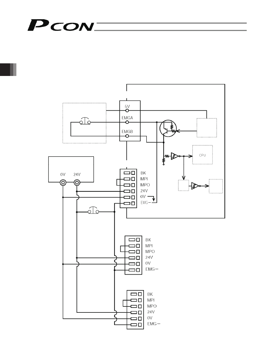
3.8
Wiring the Emergency Stop Circuit
3.8.1
Cutting Off the Drive Signal (Standard)
Connect one side of the external EMG switch to the positive side of the 24-VDC power supply, and connect the other side to
the BK terminal.
(Note) The EMG switch on the teaching pendant works only on the controller connected to the switch.
PCON-CY controller
Power-supply
terminal block
Power-supply
terminal block (2nd)
SIO connector
Teaching pendant
EMG switch
24-VDC input power
supply
(Max. 2 A per unit)
External EMG switch
Connection
detection
signal (H)
SIO
connector
connection
detection
circuit
EMG signal
detection (H)
Time
constant
Drive stop
signal (L)
Motor
drive
circuit
Power-supply
terminal block (3rd)
See also other documents in the category IAI America Hardware:
- ERC2 (188 pages)
- ERC2 (138 pages)
- ERC3 (438 pages)
- ERC (153 pages)
- RCA-E (53 pages)
- RCA-P (42 pages)
- RCB-101-MW (38 pages)
- RCP2-C (178 pages)
- RCS-E (102 pages)
- RCA-A4R (72 pages)
- RCA-RA3C (114 pages)
- RCA-SRA4R (56 pages)
- RCA2-RA2AC (100 pages)
- RCA2-SA2AC (92 pages)
- RCA2-TA4C (134 pages)
- RCD-RA1D (40 pages)
- RCP2-BA6 (72 pages)
- RCP2-GRSS (130 pages)
- RCP2-HS8C (126 pages)
- RCP2-RA2C (120 pages)
- RCP2-RTBS (80 pages)
- RCP2W-SA16C (46 pages)
- RCP3-RA2AC (60 pages)
- RCP4-RA5C (82 pages)
- RCP4-SA5C (94 pages)
- RCP4W (96 pages)
- RCS2-F5D (142 pages)
- RCS2-GR8 (46 pages)
- RCS2-RN5N (80 pages)
- RCS2-RT6 (60 pages)
- RCS2-SA4C (258 pages)
- RCS2-TCA5N (62 pages)
- RCL-SA1L (66 pages)
- RCL-RA1L (56 pages)
- RCLE-GR5L (46 pages)
- IK Series (16 pages)
- FS (84 pages)
- IF (76 pages)
- ISB (114 pages)
- ISDA (126 pages)
- ISDB (116 pages)
- ISPWA (90 pages)
- ICS(P)A (16 pages)
- NS (78 pages)
- RS (46 pages)