2 display indication modes – FEC MICRO NR User Manual
Page 72
Chapter 7: System Operations
Page 7-4
7.2 Display indication modes.
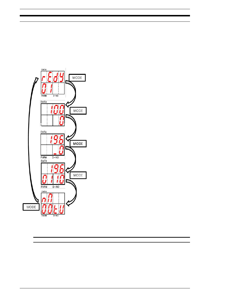
Five modes can be selected by pressing the MODE push-button. By using the [
] and [
] keys to
change the D-NO selected, the DATA display contents for parameters may be varied up or down.
The displays will remain blank and mode selection will be disabled while the nutrunner is active
(BUSY). If an Abnormal condition occurs, the display will automatically change to the Abnormal
(Abn) display mode displaying the abnormal code and sub-code.
While the MNR Unit is in cycle it will display the cycle status. The display will indicate where the
cycle is in its
’ fastening sequence. Refer to section 7.2.1 for a listing of Status display
abbreviations
The MNR unit is in Status Display Mode when no digits
are displayed in the D-NO area of the display. The STATUS
display indicates when the system is ready to run, if an
abnormal condition occurs or if an emergency stop has
halted the system.
When the power is turned on the default display mode is
the Status display mode.
The Real Time Display Mode is active when only one digit
appears in the right hand location of the D-NO area of the
display. In this mode torque, angle, date and SD card
status will be shown. The display contents can be scrolled
through by using the [
] and [
] keys.
The Fastening Results Display Mode is active when the
D-NO displays one digit in the right hand location and one,
two or three dashes in the left hand location. The results
details can be scrolled through by using the [
] and [
] keys
to change the D-NO. This mode does not function while the
nutrunner is Busy.
The Parameter Display Mode is active when the D-NO
displays digits in both the right and left hand locations. The
parameter data can be scrolled through by using the [
] and
[
] keys to change D-NO.
The Torque unit, RS232C, SD setting. The display con-
tents can be scrolled by using the [
] and [
] keys to
change.
FIG. 7-2 Display Modes