FEC MICRO NR User Manual
Page 27
FEC Micro Nutrunner Operations Manual
Chapter 3: System Description
(Rev 2: 02/12)
Page 3-3
M
O
T
O
R
U
V
W
F
G
1
2
3
4
P
O
W
E
R
M
P
C
P
0
V
1
2
3
RESOLVER
T/D
MON
SW1
SW2
SW3
CN2
PLC
STATUS
CN1
MEMORY
CARD
USB
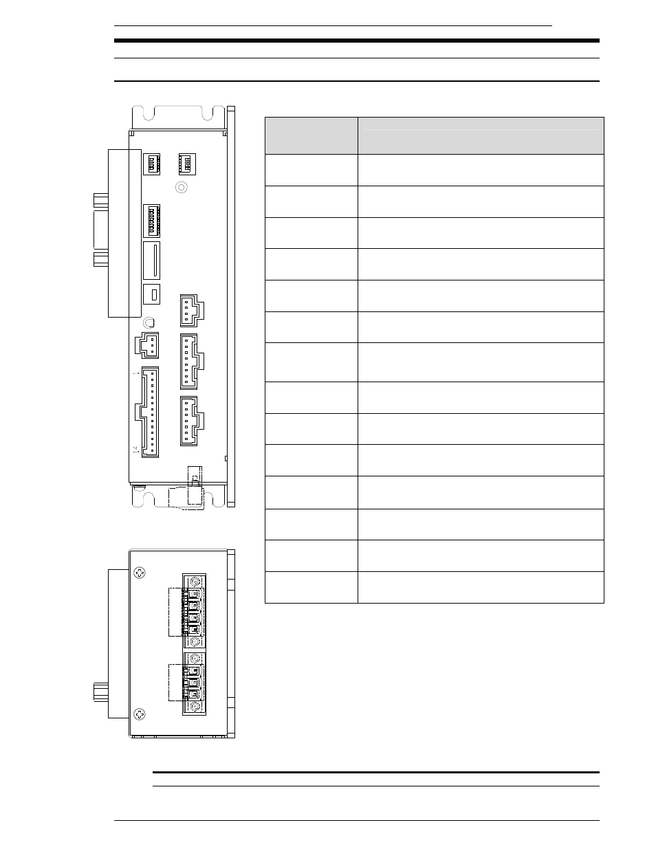
3.2
MNR UNIT Front panel
3.2.1 MNR Front Panel Switches and Connectors
FIG. 3-2-1 Axis unit Front panel controls
ITEM AS
MARKED ON
UNIT
DESCRIPTION
CN1
Amplifier programming port (Not Used)
CN2
Expansion Connector (Not currently used)
SW1
Sets Start signal type, Angle count type & display
SW2
Not Used – (Set all OFF)
SW3
Not Used – (Set all OFF)
RESOLVER
Resolver connection for tool Motor / Resolver
cable. (Angle of Rotation input)
MON.
Monitor Output
Torque Analog Voltage and Angle Pulse Output
for connection to independent monitor device.
T/D
Connection for tool Transducer cable.
(Torque signal input)
MOTOR
Motor Connection for tool Motor/Resolver cable.
(Motor Drive)
PLC
Connection for Inputs and Output (I/O) signals. .
MEMORY
CARD
Expanded memory for data storage and X-Y
Curve storage
USB
Communication port for Computer Software
connection
STATUS
Status LED (See 3.2.2 for more info)
POWER
Connection for Input Power.
24VDC 5A