FEC MICRO NR User Manual
Page 38
Chapter 4: System Setup and Wiring
Page 4-4
4.2
Power Requirements and Connections
4.2.1 MNR Unit
WARNING:
Follow Lockout/Tagout and other safety precautions when connecting
and/or disconnecting cabling, wiring, and equipment.
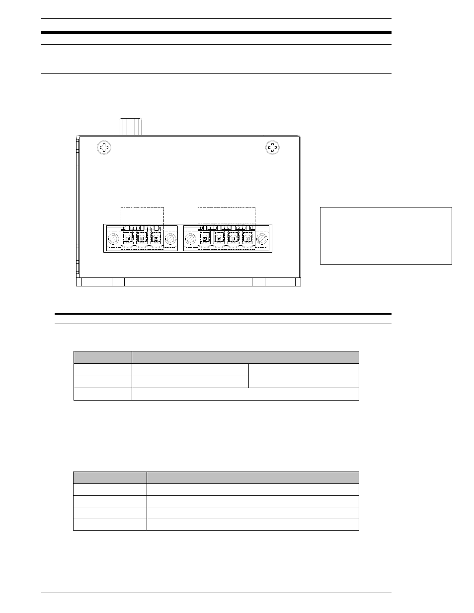
Fig. 4-2-1 MNR Unit Input Power & Motor Connections
POWER PIN
DESCRIPTION
1
Motor Power 24VDC
4.5amp min. power required
2
Control Power 24VDC
3
0VDC Common
Recommended conductor size = 18 AWG
CAUTION: If the equipment is powered on and off repeatedly, internal circuit
protection devices may trip due to high in-rush current overload. It may take up to five
minutes of “off” time to clear the self-protection circuit. Please wait 15 seconds after
power down to power up.
MOTOR PIN
DESCRIPTION
1
Motor “U” Phase
2
Motor “V” Phase
3
Motor “W” Phase
4
FG
MOTOR
U V W FG
1 2 3 4
POWER
MP CP 0V
1 2 3
Mating Connectors:
Manufacturer: Phoenix Contact
Power Model #: MSTB 2, 5/3-STF-5.08
Motor Model #: MSTB 2, 5/4-STF-5.08
Type: Screw
Terminal Type