FEC MICRO NR User Manual
Page 42
Chapter 4: System Setup and Wiring
Page 4-8
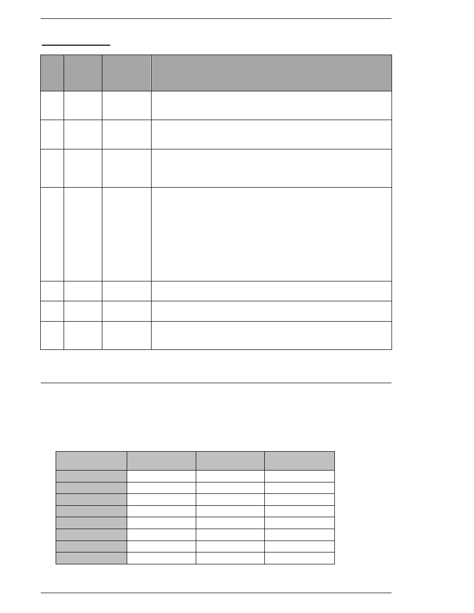
OUTPUT SIGNALS
P
LC
P
in
#
SIGNAL
TYPE
SIGNAL
NAME
DESCRIPTION
8 OUTPUT REJECT
Output when the fastening result is a REJECT. Indicates that the
spindle has failed the fastening limits. This output remains active un-
til the START signal or RESET signal is input.
9 OUTPUT ACCEPT
Output when the fastening result is a ACCEPT. Indicates that the
spindle is within the fastening limits. This output remains active until
the START signal or RESET signal is input.
10 OUTPUT ABNORMAL
Output when an ABNORMAL condition occurs. Indicates that the
System has detected an internal fault and can no longer proceed.
An Abnormal condition must be corrected before the System will
resume normal operation.
11 OUTPUT READY
Output when the system is in READY condition to operate and inputs
are enabled. This signal is inactive (off) in the following cases:
- Upon power-up while the processor is initializing (approx. 5sec.)
- During a Reverse operation
- When an Abnormal occurs
- During User Console communication
- When the BUSY signal is active (on)
- When the Reset or CAL button is being pressed
- When operation of the MNR Unit by an external input is
impossible
12 OUTPUT BUSY
Output after a START signal is received and active until the fastening
cycle is complete and the READY signal is output.
13
OUTPUT WARNING
Output when available memory size of the Micro SD card for data
storage becomes less than 10% of total memory size.
14
OUTPUT
COMMON
Output signal common. Connection to +24VDC or 0 VDC required
(Reference PLC wiring example)
4.3.2 Work / Parameter Select Table
WORK SELECT Inputs provide a means to change the preset parameter sets when the system
uses multiple fastening specifications. These three bits are used in a binary fashion to select up
to 8 different parameter sets.
With none of the bits enabled, the system will automatically use parameter set #1. The WORK
SELECT inputs must be selected at least 250ms BEFORE the start signal is activated.
PARAMETER
NO.
WORK
SELECT 2
WORK
SELECT 1
WORK
SELECT 0
1
OFF
OFF
OFF
2
OFF
OFF
ON
3
OFF
ON
OFF
4
OFF
ON
ON
5
ON
OFF
OFF
6
ON
OFF
ON
7
ON
ON
OFF
8
ON
ON
ON
ON = Enabled
OFF = Disabled