FEC MICRO NR User Manual
Page 29
FEC Micro Nutrunner Operations Manual
Chapter 3: System Description
(Rev 2: 02/12)
Page 3-5
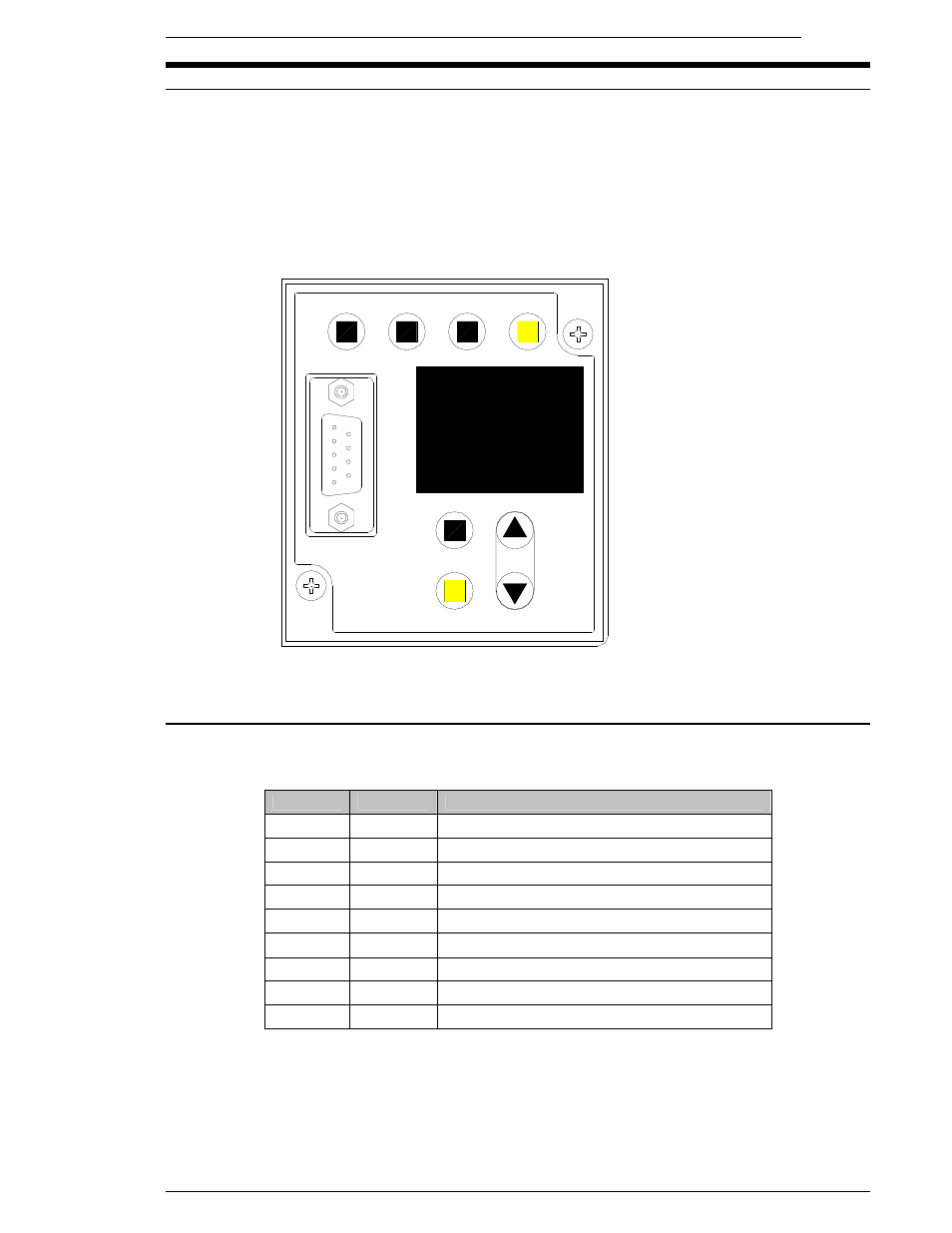
START
REV.
CAL
RESET
DATA
PARM.
D-NO.
MODE
SET
RS232C
SAN3-DP2
DATA
3.3
MNR Keyboard-Display unit description
The display unit incorporates programming and monitor functions display into the MNR controller.
It comes standard within the MNR unit. Programming of parameters can be accomplished using
the programming keys as well as displaying the fastening result data from the LED display. The
included RS232 9 pin connector allows User Console communication or the output of fastening
data to host or monitor systems.
NOTE: Refer to Chapter 7 for detailed operation using the keyboard/display unit.
3.3.1 RS232C Serial Pin out
Connector: DB-9P (Male)
Mating Connector: DB-9S (Female)
PIN
SIGNAL
DESCRIPTION
1
NOT USED
2
RXD
NOT USED
3
TXD
TRANSMIT DATA
4
DTR
DATA TERMINAL READY (ALWAYS ON)
5
GND
SIGNAL GROUND
6
DSR
NOT USED
7
RTS
REQUEST TO SEND (ALWAYS ON)
8
CTS
CLEAR TO SEND
9
NOT USED
Note: The CTS signal needs to be activated in order for the fastening data to be output. If it is
not activated, up to 16KB of data will be stored in the output buffer. Once the buffer is full, the
data will be overwritten in a First In, First Out (FIFO) process. The CTS signal may be con-
nected to the RTS signal if data is to be “dumped” at every fastening.